systemair 27
2.3.6 Connection of electrical installation
Electricalinstallationsmustbeconnectedsoasnottopreventorhinderthechecking,servicingorreplacementof
functional components. Connection must be carried out in accordance with the design documents, the manufacturer’s
guidelines and the provisions of the technical regulations and standards.
Theinstallerandusershouldbeawareoftherisksarisingfromlightning.Theinstallationofovervoltageprotection
devices,whichsafelydiverthighvoltageenergyintheeventofalightningstriketoearth,mustbeimplementedin
accordance with local regulations.
The penetration of power and control cables through the casings or internal partition walls must be carried out so as
to ensure the protection of cables from damage in contact with sharp metal sheet edges. All the penetrations must be
airtight. For penetrations of cables through partition walls and other structural elements inside the casing, membrane
rubberttingsorcableglandsofappropriatesizesmustbeapplied.Inmostcases,theholesforsuchttingsare
punchedandthettingsareinstalledinthefactory.
For penetrations of cables through casing walls, cable glands and custom-made extension pieces must be applied. For
penetrationsofcablesthroughtwocasingwalls,e.g.inthecaseofstackedorparallelunits,applycombinationsof
rubberttingsandstiffPVCtubesorcableglandsandcustom-madeextensionpieces.
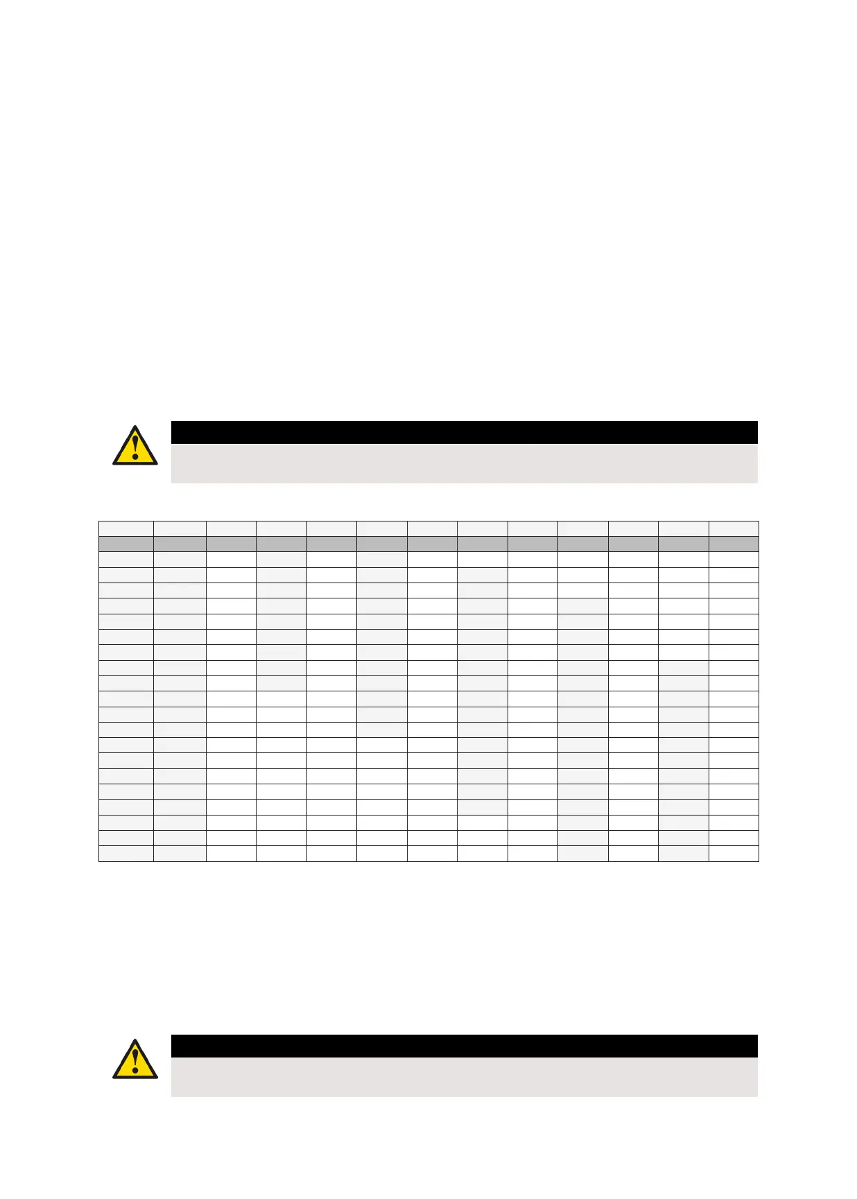
The size of a power cord depends on the electrical power, and the length can be determined in the table below.
Caution
Electric power is provided for three-phase current.
Sensors, actuators and other external measuring equipment can be connected with a 0.75 m2 cable.
Power Current 1.5 2.5 4 6 10 16 25 35 50 70 95
kW (3p) A mm
2
mm
2
mm
2
mm
2
mm
2
mm
2
mm
2
mm
2
mm
2
mm
2
mm
2
1,5 2.3 100 m 165 m 265 m 395 m - - - - - - -
3 4.6 33 m 84 m 135 m 200 m 335 m 530 m - - - - -
4,5 6.8 30 m 57 m 90 m 130 m 225 m 355 m 565 m - - - -
6 9 25 m 43 m 68 m 100 m 170 m 265 m 430 m 595 m - - -
7,5 11.5 20 m 34 m 54 m 80 m 135 m 210 m 340 m 470 m 630 m - -
9 13.5 17 m 29 m 45 m 66 m 110 m 180 m 285 m 395 m 520 m - -
10,5 16 14 m 24 m 39 m 56 m 96 m 155 m 245 m 335 m 450 m - -
12 18 - 21 m 34 m 49 m 84 m 135 m 210 m 295 m 395 m 580 m -
13,5 20 - 19 m 30 m 44 m 75 m 120 m 190 m 260 m 350 m 515 m -
15 23 - - 27 m 39 m 68 m 105 m 170 m 235 m 315 m 460 m 630 m
18 27 - - 23 m 32 m 56 m 90 m 140 m 195 m 260 m 385 m 530 m
21 32 - - - 28 m 48 m 76 m 120 m 170 m 225 m 330 m 460 m
24 36 - - - - 42 m 67 m 105 m 145 m 195 m 290 m 400 m
27 41 - - - - 38 m 60 m 94 m 130 m 175 m 255 m 355 m
30 45 - - - - 34 m 54 m 84 m 120 m 155 m 230 m 320 m
36 55 - - - - - 45 m 70 m 92 m 130 m 190 m 265 m
42 64 - - - - - 38 m 60 m 84 m 110 m 165 m 230 m
48 73 - - - - - - 53 m 74 m 99 m 145 m 200 m
54 82 - - - - - - 47 m 65 m 88 m 125 m 175 m
60 91 - - - - - - - 59 m 79 m 115 m 160 m
2.3.7 Vibration and structure-borne noise
Reductionofvibrationtransmissiontothebuildingispossiblebyconnectingthedevicetotheductnetworkviaexible
connections and by placing the device on appropriate vibration isolators.
Tomitigatestructuralnoise,werecommendusingrubberorelastomericpadsunderthedevice.Tokeeptheunit
properlyalignedandworking,carefullychecktheairconditioningalignment(openingandclosingthedoor,connecting
the modules).
Caution
We recommend that the anti-vibration pads, including the material and layout plan, are selected and
determined through a professional company.
 Loading...