systemair 13
Storage before installation
Before installation, air handling units must be stored indoors, in dry areas, or be protected against the elements or
other damage in some other appropriate manner. Remove the plastic foil wrapping and cover the equipment with a
waterproof canvas or similar cover, and ensure adequate clearance between the cover and equipment casing. This is
necessarytofacilitatesufcientaircirculationinordertoavoidairhumiditycondensationandtheconsequentcorrosion
of the external surfaces.
Caution
Until connecting the equipment to the ducting, protect the air inlet and outlet openings against the
ingress of dust or other pollutants.
The allowable storage temperature ranges from -25 ° C to +55 ° C.
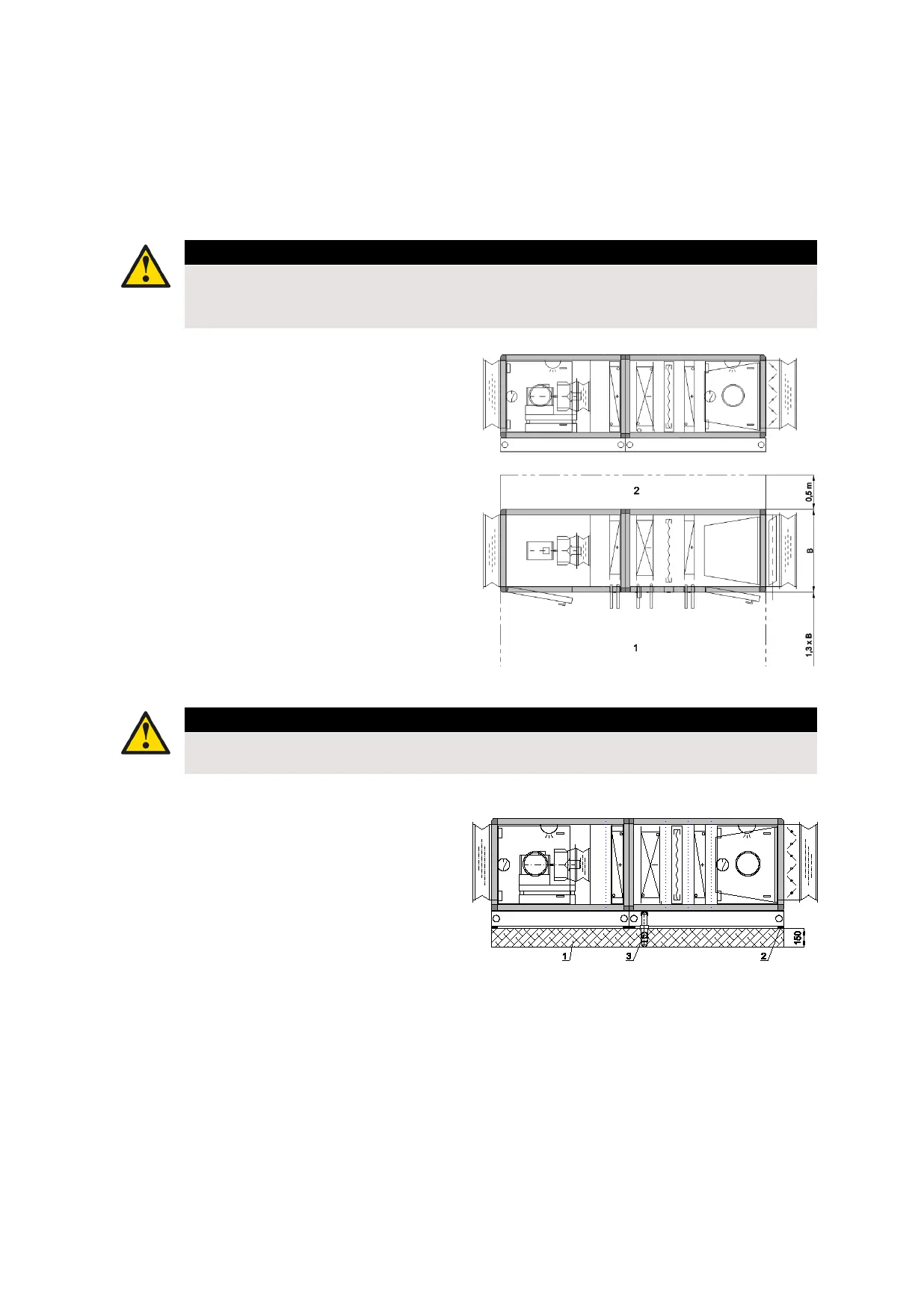
2.2 Mounting
Clear the space in front of and above the unit
In placing the equipment on the site, provide a clear
area in front of the air handling unit in order to enable
servicing, control and, when necessary, the drawing out
andreplacementoffansandheatexchangers;thewidthof
the area should at least equal the external width of the air
handling unit. In any event, the width of the clear area in
front of air handling unit must not be less than 900 mm.
In the event the electric control cabinet is positioned on
top of the air handling unit, a free space at least 700 mm
in height must be provided between the unit’s top edge
and the ceiling of the room in order to enable safe access
to the cabinet.
In order to facilitate the assembly and joining of shipment
units, a clear space of at least 500 mm in width is also
recommendedatthebacksideoftheunit.
Caution
Wherenotpracticable,themethodofjoiningshipmentunitsmustbespeciedintheorder.
Theaccesstoshipmentunitjoiningpointsfromtheinsidetheunitcasingmustbespecied.
1 Service side 2 Non-serving side B Unit width
The foundation for the unit
Thesupportingsurfacemustbeat,horizontal,freeof
vibrations and capable of supporting the load created by
the air handling unit. The weight of the entire air handling
unit and its individual shipment units are listed in the
technical documentation accompanying the equipment.
Airductsmustbesoundinsulatedandmaynotbexed
directlyonconcretebeams,structuraltimberworkorother
critical structural elements.
In the event of mounting on elevated support platforms,
the means for safe access and servicing must be provided.
In the case of acoustically demanding buildings, the
foundation slab should be isolated from the rest of the
building structure by means of structural noise insulation
ofappropriatethickness,dependingontheairhandling
unit mass and excitation frequency, as well as the
insulation material’s natural frequency.
Inthecaseofunitsthatincludeasprayhumidiersection,
all the other sections should be mounted on a special
steel base or provided an appropriate foundation.
1 Base 2 Antivibration pads B Drain siphon
 Loading...