32 systemair
Cable length and cross-section
The frequency converter has been tested with a given length of cable and a given cross-section of that cable. If the
cross-sectionisincreased,thecablecapacitance-andthustheleakagecurrent-mayincrease,andthecablelength
must be reduced correspondingly.
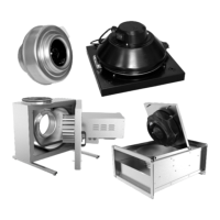
Grounding of shielded / reinforced control cables
In a general sense, the control cables must be braided / reinforced and the shield must be connected at both ends to
the metal housing of the unit using a cable clamp.
Correct grounding
Control cables and cables for serial communication must
have cable clamps at both ends for the best possible
electrical contact.
Incorrect grounding
Do not use cables with twisted ends. They increase the
array impedance at higher frequencies.
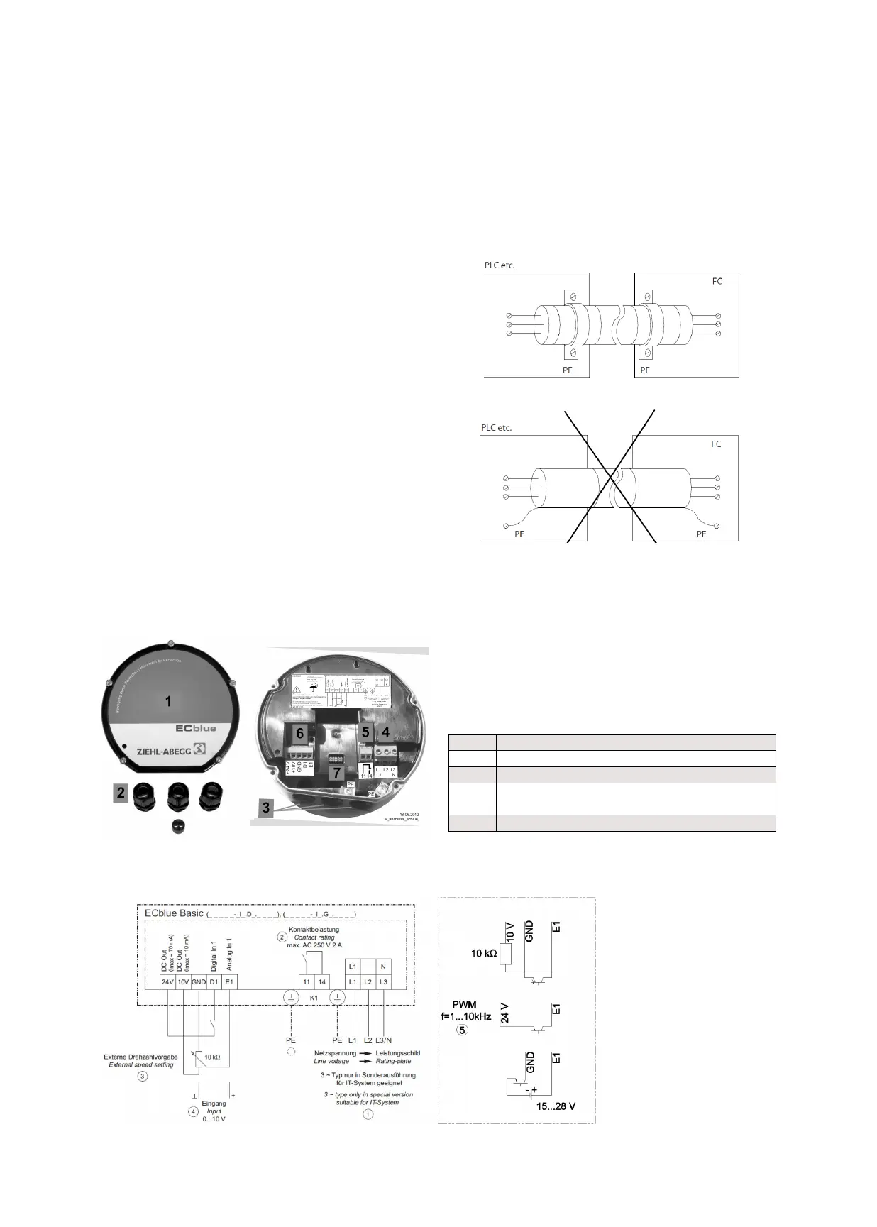
3.3.2 Connection of EC fan
Connection of Ziehl-Abegg ECblue
Connection of EBM paps
1 Cover of controller housing
2 Cable glands + seal insert for two cables (applicable only if necessary)
-motorsize“D”:3xM16+1xsealinsertwithtwoholes5mm
-motorsize“G”:3xM20+1xsealinsertwithtwoholes6mm
3 Cable entry points with plastic fastener
4 Mains connection
5 Connection alarm relay
6 Connection contols
+24V Power supply +24V
+10V Power supply +10V
GND Grounding
D1
Digital input (if we connect + 24V to D1 we activate the start
condition)
E1 Analog input (0-10V)
7 Slot for add-on module
 Loading...