Chapter 3 - Parameter List
32
Code Description
Keypad
Display
Setting Range Units
Factory
Default
Adj.
During
Run
Page
2 (Stop)
I/O-49
Waiting Time after Loss of Freq.
Reference
I 49 0.1 to 120.0 [sec] 0.1 1.0 [sec] Yes
0~6 (LS- Bus ASCII)
I/O-50 Communication Protocol Selection I 50
7~11 (Modbus-RTU)
-
7 (Modbus-
RTU)
Yes 72
I/O-53 Communication Delay Time I 53 0.02 to 1 [sec] 0.01 0.02 Yes
I/O-99 Return Code rt - 1 Yes 72
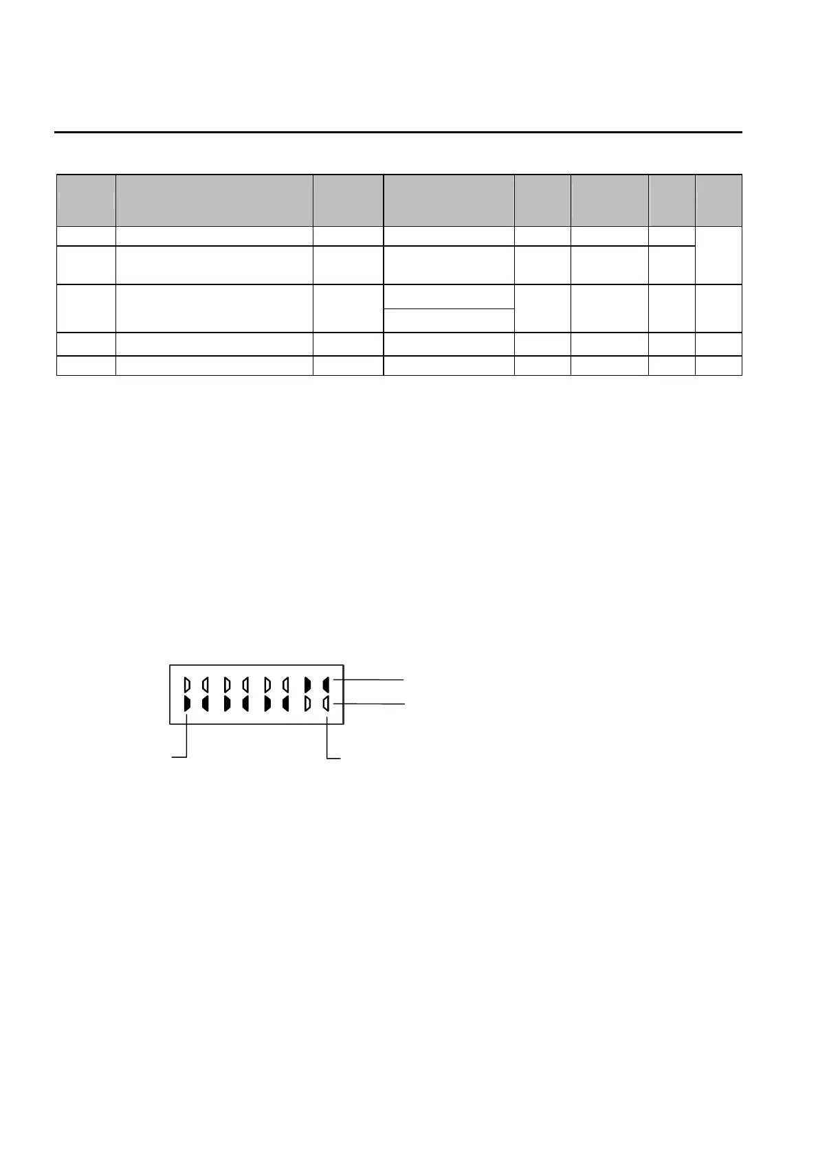
Note: Parameters that are set by a bit are ON (1) when the upper LED is lit as shown below.
(F59, H19, H22, I15, I16, I45 are the parameters that are set by bit.)
Note: Communication protocol can be set at I/O 50..
0 => Data : 8, Parity : None, Stop : 1 7 => Parity : None, Stop : 2
1 => Data : 7, Parity : None, Stop : 2 8 => Parity : None, Stop : 1
2 => Data : 7, Parity : Even, Stop : 1 9 => Parity : None, Stop : 2
3 => Data : 7, Parity : Odd, Stop : 1 10 => Parity : Even, Stop : 1
4 => Data : 8, Parity : None, Stop : 2 11 => Parity : Odd, Stop : 1
5 => Data : 8, Parity : Even, Stop : 1
6 => Data : 8, Parity : Odd, Stop : 1
Dummy Data (FF) is added to the inverter response only when 7 is selected at I 50.
Example) when the keypad displays ‘00000011’
Note: FU1-20, FU1-21, FU1-25, FU1-36, FU2-54, FU2-83, I/O-05 and I/O-10 are set at 50Hz for Standard (EU) types and 60Hz
for US types. Please check these parameters before commissioning to verify that you have the right product.
Bit 0
Bit 7
1:ON
1:OFF