DSC Q Series Getting Started Guide
39
Voltage Configuration Unit
A voltage configuration unit is required if you use 230 Vac, rather than 120 Vac. Follow these steps to install
the transformer in the Power Control Unit (PCU):
WARNING: High voltages are present in this instrument as indicated by the label.
Be sure to unplug the instrument before performing these instructions. See the
WARNING on page 9.
1. Remove the contents from the shipping box and verify
that all of the components are present.
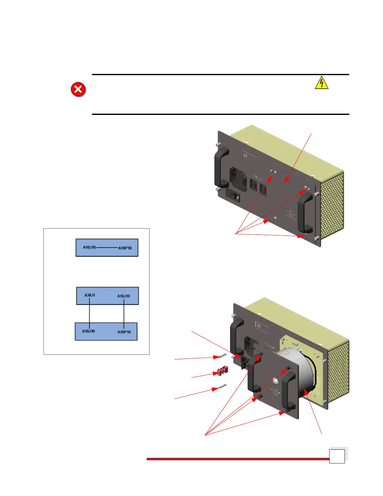
2. Remove the access plate located on the rear of the
instrument by removing the four (4) screws that secure
it in place. See the figure to the right.
3. Disconnect the A10J10 connector from A10P10 located
inside the PCU. Now connect the A10J10 connector on
the voltage configuration unit to A10P10 located inside
the PCU. Then connect A10J10 located inside the PCU
to A38J1 on the anti-surge subassembly. See the dia-
gram below for clarification.
4. Install the subassembly into the
PCU and tighten the four (4) captive
fasteners to secure it.
5. Remove the fuse holder from the
power entry module and replace
the 10 amp fuses with 6.3 amp fuses,
which are supplied in the kit. Dis-
card the 10 amp fuses. See the figure
to the right.
Access Plate
Screws
Power Entry
Module
Fuse
Fuse Holder
Fuse
Captive Fasteners
Voltage Configuration Unit
Original
Power Control Unit
Voltage Configuration Unit
Power Control Unit
Final