Instruction and Operating Manual
TA-U1...U280
Misprints and technical changes reserved
10
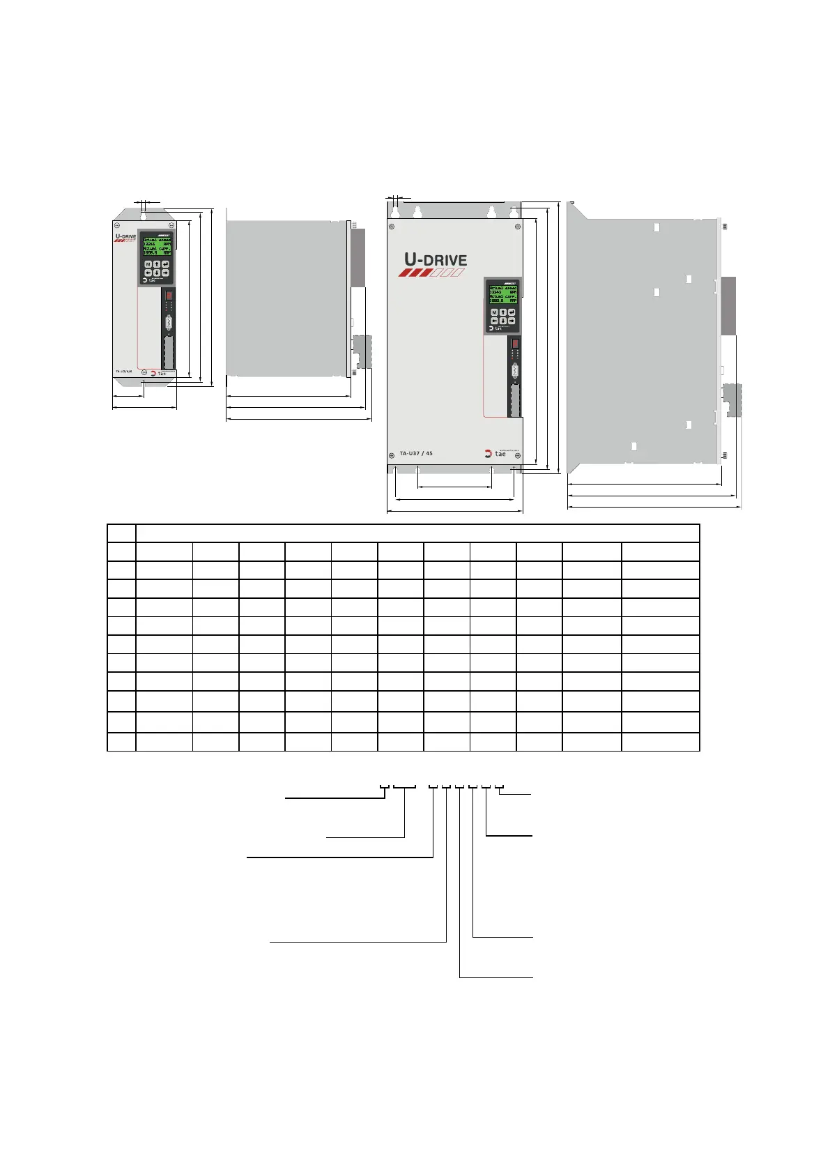
3.2.2 Dimensions TA-U2…U400
Structure of complete part number:
4Q
SR
B
Bus
RS 422 / 485
A
I-L
V
U
W
RS 422 / 485
W
U
V
I-L
A
B
SR
4Q
Bus
universal drive
0 Ready For Run
1 Run (Enabled)
C1 DRV-Te mp Warning
C2 MOT-Te mp Warning
C3 Value Out Of Range
C4 Safe Stop
C5 DRV Locked Ref>0
C6 Pow-Stage Disabled
F0 Motor Overtemp.
F1 Overcurrent
F2 Drive Overtemp.
F3 Undervoltage
F4 Overvoltage
F5 Rippel Current
F6 Po sion Sensor
F7 Speed Sensor
F8 Electronic
F9 IGBT Short-Circ uit
E1 External Error
universal drive
0 Ready For Run
1 Run (Enabled)
C1 DRV-Te mp Warning
C2 MOT-Temp Warning
C3 Value Out Of Range
C4 Safe Stop
C5 DRV Locked Ref>0
C6 Pow-Stage Disabled
F0 Motor Overtemp.
F1 Overcurrent
F2 Drive Overtemp.
F3 Undervoltage
F4 Overvoltage
F5 Rippel Current
F6 Po sion Sensor
F7 Speed Sensor
F8 Electronic
F9 IGBT Short- Circuit
E1 External Error
H2
B
B1
H2
H1
H
T
T2
T1
S
B
B2
B1
T
T2
T1
S
H1
H
PG 4001
PG 4001
Housing sizes
U1/2/4/6 U8/10 U15 U22 U30 U37/45 U55/65 U75/90 U110 U150/170 U200/250/280
B 127 195 205 250 250 270 355 363 425 555 1100
B1 63,5 162,5 172 217 217 237 322 329 380 505 595
B2 - - - - - - - - - - 965
H 341 378 378 390 495 520 564 660 842 981 1215
H1 325 358 358 370 475 500 544 640 815 954 1173
H2 301 330 330 341 446 471 516 611 780 919 1122
T 268/289* 267 325 306 292 338 379 369 413 418 420
T1 240/261* 239 297 278 264 310 351 341 385 390 392
T2 313/334* 312 370 351 337 383 424 414 458 463 465
S 6 9 9 9 9 9 9 9 12 13 13
Analog / digital-board I/O
0 = without
1 = with analog/digital board
EMC-Filter
0 = without
1= with EMC-filter
Housing sizes
1 = up to size TA-U90
2= as of size TA-U110
Feedback system
A = Standard (Hall sensors)
B = RS 422
C = Resolver
D = SinCos-Hiperface
E = SinCos-EnDat
Z = Sensorless
Rating (output power)
with external supply for electronics
only available for TA-U2...U15
only available for TA-U2/U4/U6
Bus-system
F = Standard (without bus)
G = Profibus
I = CANopen
K = DeviceNet
L = Ethernet / Powerlink
M = EtherCAT
N = Ethernet IP
O = Profinet
Voltage
0 = 170 - 250V 3Ph 50/60 Hz
1 = 300 - 480V 3Ph 50/60 Hz
2 = 170 - 250V 3Ph 50/60 Hz
1)
3 = 300 - 480V 3Ph 50/60 Hz
1)
4 = 240 - 390V DC Buss supply
5 = 420 - 780V DC Buss supply
Control mode
0 = 1Q
1 = 4Q (without brake chopper)
2 = 4Q (with brake chopper)
2)
3 = 4Q (with brake chopper & resistor)
3)
 Loading...