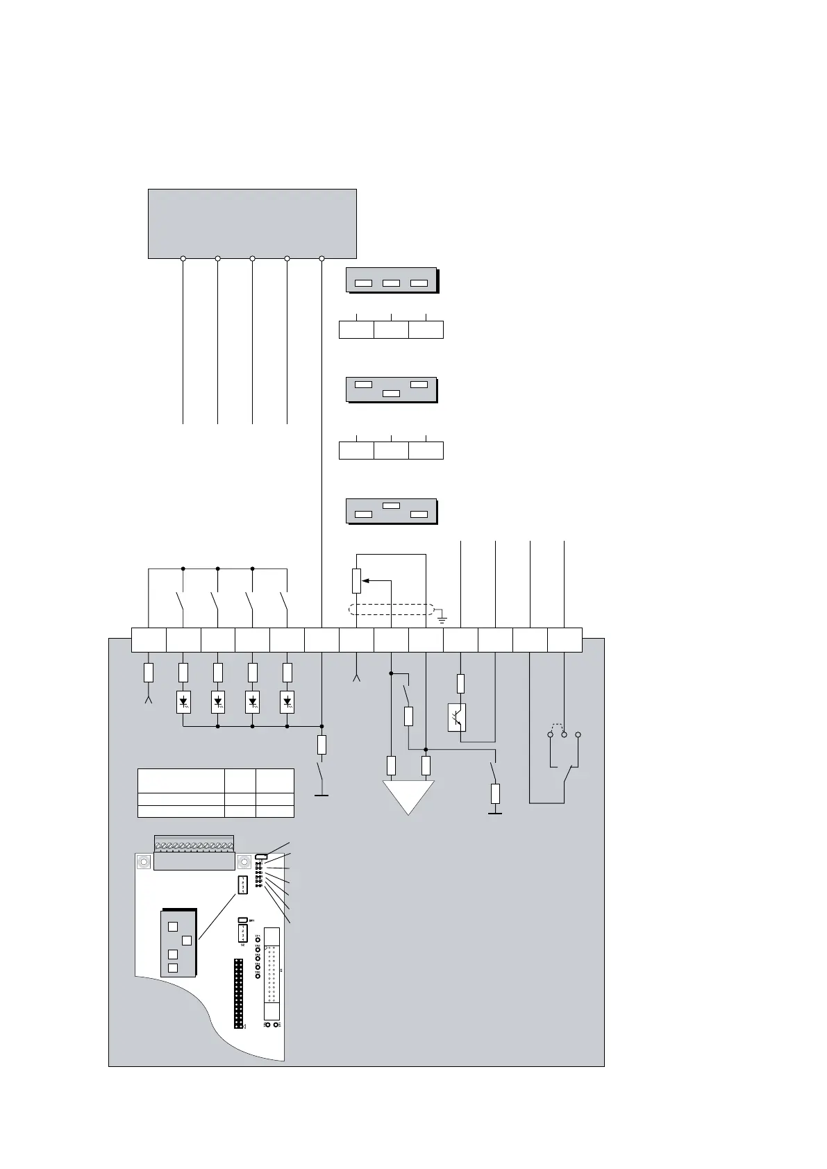
UD-CPU PCB - 0101
Controlboard
for TA-U...
4 5 6 7 8 9 10 11 12 13321
+10V max 3mA
Programmable input
Programmable input
Programmable input
Programmable input
(Reset default)
(Run right default)
(Run left default)
(Stop default)
(ready for run default)
(Common fault default)
Alternative
PLC control
AGND
DIP-S1
78
9
OFF
ON
123
00
1
DIP-S1
OFF
ON
123
11
0
78
9
DIP-S1
OFF
ON
123
000
Programmable output
Programmable output
Programmable output
Programmable output
(Brake On) *
S1-2
GND
S1-4
10R
S1-1
10R
10R
100R
* At Brake function active (parameter 860.00) is relay output at terminal 12/13 generally
configured to control the brake.
nominal value
Potentiometer
0-20mA/
4-20mA
0-10V External
2
1
3
IN
PTC
OUT
+24V
max 100mA
X5
5
4
1
2
3
6 12
9
10
8
11 13
X4
7
Yellow - input terminal 2
Yellow - input terminal 3
Yellow - input terminal 4
Yellow - input terminal 5
Yellow - output terminal 10/11
Yellow - output terminal 12/13
S1
ONOFF
4
3
2
1
DIP Switch S1
(Factory adjustment)
00 0
1
Supply
Digital inputs
S1-4 DC
external OFF 15-30V
terminal 1ON
internal
max 50mA
max 250V/1A
BR5
right
left
BR5
 Loading...