Instruction and Operating Manual
TA-U1...U280
Misprints and technical changes reserved
16
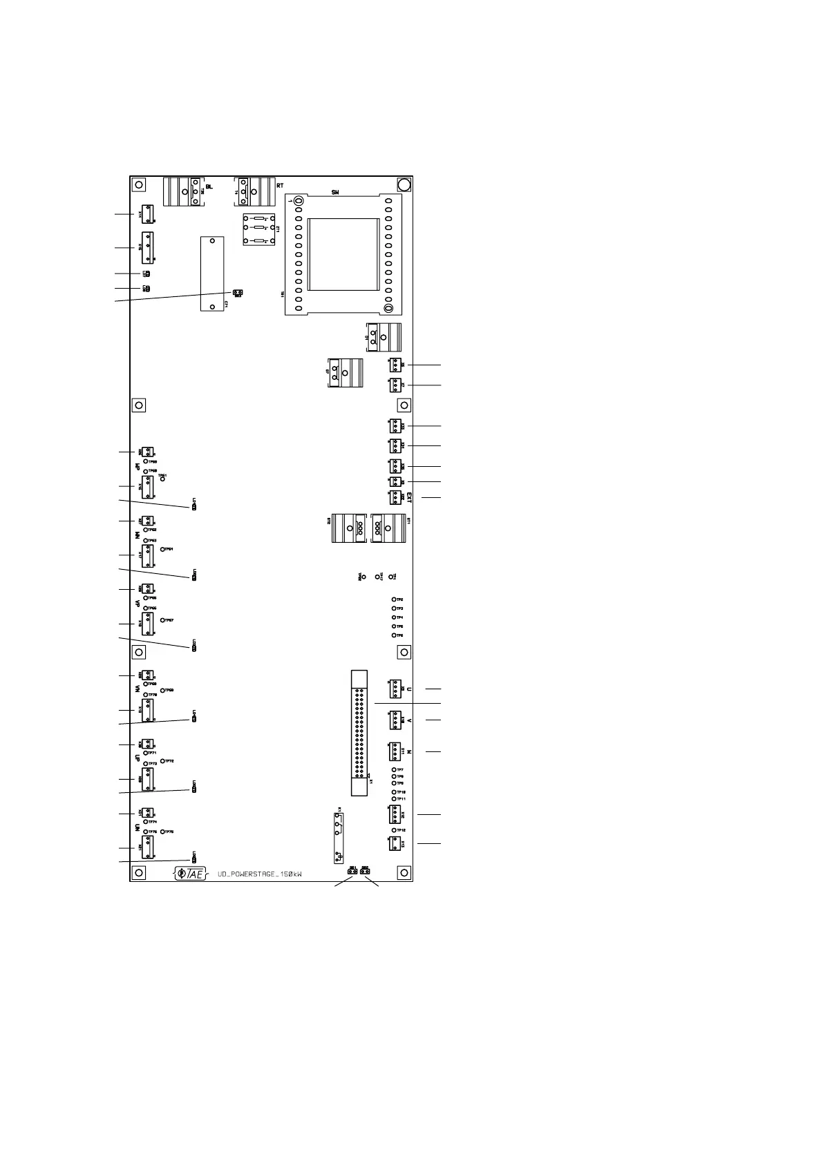
3.3.4 Powerstage start at U110
X1 Connection to controlboard
X6 +/-24V
X7 +/-24V
X8 Charging relay
X9 Current U
X10 Current V
X11 Current W
X12 PT100/Thermal switch
X13 Safe Stop
X14 External elektronic supply
X15 Buss voltage
X16/X26 IGBT WP
X17/X27 IGBT WN
X18/X28 IGBT VP
X19/X29 IGBT VN
X20/X30 IGBT UP
X21/X31 IGBT UN
X22 Supply Charging relay
X33 +/-24V fan (switched)
X34 +/-24V fan (switched)
X35 +/-24V fan (switched)
LD1 IGBT WP
LD2 IGBT WN
LD3 IGBT VP
LD4 IGBT VN
LD5 IGBT UP
LD6 IGBT UN
LD7 Buss voltage "red"
LD8 Power supply active "green"
BR1 Indication Safe Stop bridged
BR2 Safe Stop bridged
BR3 Mains voltage 200-250V
X6
X7
X14
X15
LD7
LD8
BR3
X16
LD1
X26
X17
LD2
X27
X18
LD3
X28
X19
LD4
X29
X20
LD5
X30
X21
LD6
X31
X9
X10
X1
X11
X12
X13
BR1 BR2
X33
X34
X35
X8
X22
wh
bu
gn
bn
wh
bu
gn
bn
wh
bu
gn
bn
 Loading...