June 2003 IPN: M5000-00-105 Desktop fast charger E - 11
Replacing the spring contacts
Remove the faulty contacts with a soldering
iron and discard.
If the replacement spring contacts have a
larger diameter and will not fit through the
PCB, the holes should be drilled out to 2.2mm.
When placing the replacement contact, it must
not be bent or otherwise damaged. Solder the
replacement contact in place using a heavy-tip
soldering iron (e.g. Weller 2PTCC8 tip). Hold
onto the contact with a pair of pliers and apply
solder to the PCB, rather than to the contact, to
avoid contact damage.
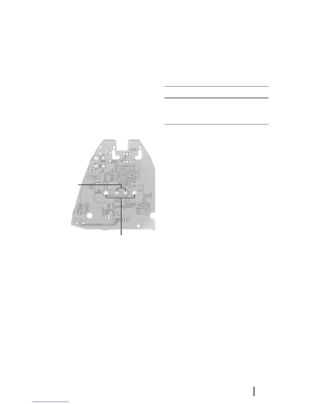
Figure E-4: The fast charger PCB
Replacing the discharge tact switch
Remove the tact switch using a desoldering
station or solderwick. Place the new part on the
board and solder it in place using a medium-tip
soldering iron (e.g. Weller PTA7 tip).
Replacing the DC jack
Remove the DC jack using a desoldering station
or solderwick. There is a lot of solder on both
sides of the board, so be sure to remove it all.
Place the new part on the board and solder it in
place using a heavy-tip soldering iron (e.g.
Weller 2PTCC8 tip).
Reassembling the charger
Refer to Figure E-3.
Hold the body of the charger upside down and
insert the conditioning button and the light
pipe; both parts self-orient. Place the PCB so it
rests on the location pins. Attach the base at
the front edge, and clip it down at the back.
Table E-4: Charger Spares and Upgrade Kits:
Capacity and
emperature
ontacts
–ve and +ve
contacts
Product code Description
TOPA-SP-202 Charger Spares Kit
TOPA-SP-203 Charger Upgrade Kit
TOPA-SP-205 Charger Software Upgrade Kit