June 2003 IPN: M5000-00-105 Tait Orca 5000 accessory connector F - 3
Tait Orca 5000 accessory connector
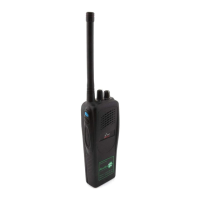
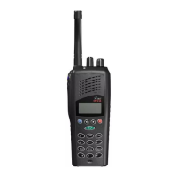
The Tait Orca 5000 portable radio has a versa-
tile accessory interface on the rear of the radio
for connecting external accessories, such as
speaker microphones and headsets.
There are four Tait accessory connector kits
available for Tait Orca 5000 portable radios:
■ Accessory Connector Kit with green P-Clip
(TOPA-AA-006G);
■ RF Accessory Connector Kit with green P-
Clip (TOPA-AA-007G).
■ Accessory Connector Kit with D-Clip
(TOPA-AA-106G); and
■ RF Accessory Connector Kit with D-Clip
(TOPA-AA-107G)
These kits are for use with the new chassis
only. See “New chassis” on page A-5 and
“Accessory connector compatibility” on page
G-8. For accessory connectors compatible with
the old chassis, refer to issue M5000-00-103 of
this service manual.
Each kit contains the accessory connector PCB
with the required spring probes soldered on.
The board supplied with the RF accessory
connector kit has four additional probes for RF
applications.
Figure F-1 shows the bottom side of the acces-
sory connector PCB and a circuit diagram of
the accessory connector is shown in Figure F-3.
Table F-1 shows the signals available at the
accessory connector, and
the signals are described in
more detail in “Accessory
connector signal descrip-
tions” on page F-6.
Screw head types
The Tait Orca 5000 Acces-
sory connector requires a
Pozi 1 driver for the green
P-Clip connector, and a Hex 2 driver for the D-
Clip connector. Additionally a Torx T6 driver
is required.
Connecting an accessory
Check that your accessory is compatible with
the accessory connector by referring to
Table F-1 “Accessory connector signal specifi-
cations” on page F-5. If connecting a headset,
refer to “Connecting a headset” on page F-5 for
connection details.
Accessory connector PCB link options
There are two optional links on the accessory
connector PCB.
To turn off the radio’s internal speaker, short
link 1 (‘LINK1’, shown in Figure F-1).
If an external switch is to be used to control the
EXT-PTT line, for example in a hands-free
vehicle kit, short link 2 (‘LINK2’, shown in
Figure F-1).
Accessory connector PCB connections
Solder pads P1 to P16 are provided on the
bottom side of the accessory connector PCB
for connection to external accessories. The
location of these pads is shown in Figure F-1.
This diagram also shows the locations of the
spring probes 1 to 16, and links 1 and 2.
Figure F-1: Tait Orca accessory connector PCB -
bottom side
Link1
P1
P10
P11
P12
P13
P14
P15
P16
P2
P3
P4
P5 P6
P7
P8
P9
1
10
11
12
13
14
15
16
2
3
4
5
6
7
8
9
A
B
A
B
Link2