F - 4 Tait Orca 5000 accessory connector June 2003 IPN: M5000-00-105
Accessory connector assembly
Assemble the accessory connector as shown in
Figure F-2.
The order of assembly is as follows.
1 Thread the cable from your accessory
through the accessory housing, making
sure it goes through in the proper direc-
tion.
2 Slide a grommet of appropriate size onto
the cable and pull firmly so the cable and
grommet fit in place.
3 Strip and tin the accessory signal wires.
4 Solder the accessory wires to the correct
pads on the accessory connector PCB
(refer to Table F-2 for headset connec-
tions).
5 Fit the accessory connector PCB links, if
required.
6 Crimp the cable at an appropriate
distance along the cable, approximately in
line with the edge of the PCB.
7 Use narrow-nose pliers to pull out the
appropriate plugs in the seal and fit it onto
the PCB.
8 Fit the grommet and PCB/seal into the
housing and secure it with the supplied
screw. Torque the screw to 3in.lb
(0.34Nm).
9 Fit the lock to the accessory connector
housing.
10 Fit the quarter turn tip, and secure with
supplied screw. Torque the screw to 3in.lb
(0.34Nm).
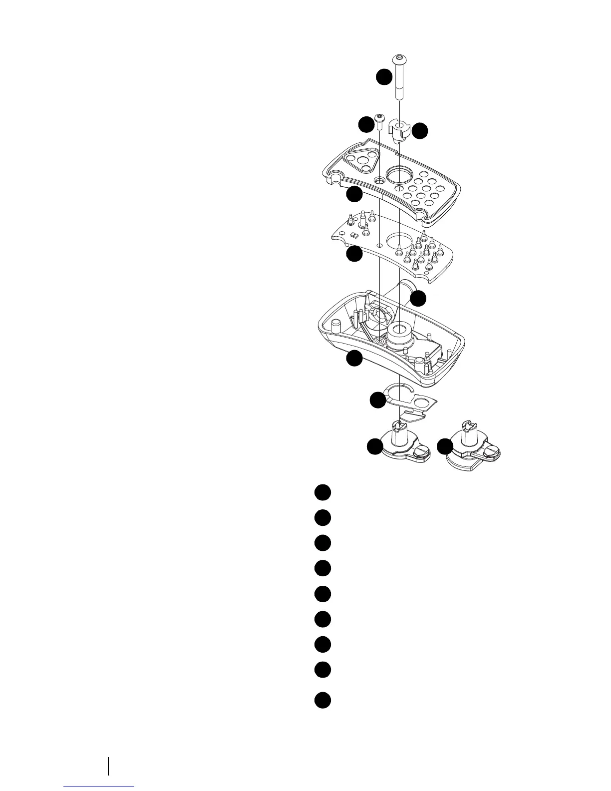
Figure F-2: Accessory connector assembly diagram
Lock (a) green P-Clip or (b) D-Clip
Spring
accessory connector housing
grommet
accessory PCB, complete with pins
PCB seal
screw M2x5 Pan Torx
quarter turn tip (lugs)
screw M3x16 Pan Pozi (green P-Clip)
screw M3x20 Hex (with D-Clip)
1
2
3
4
5
6
7
8
9
1a
2
3
5
6
9
7
8
4
1b