June 2003 IPN: M5000-00-105 Tait Orca vehicle kit F - 19
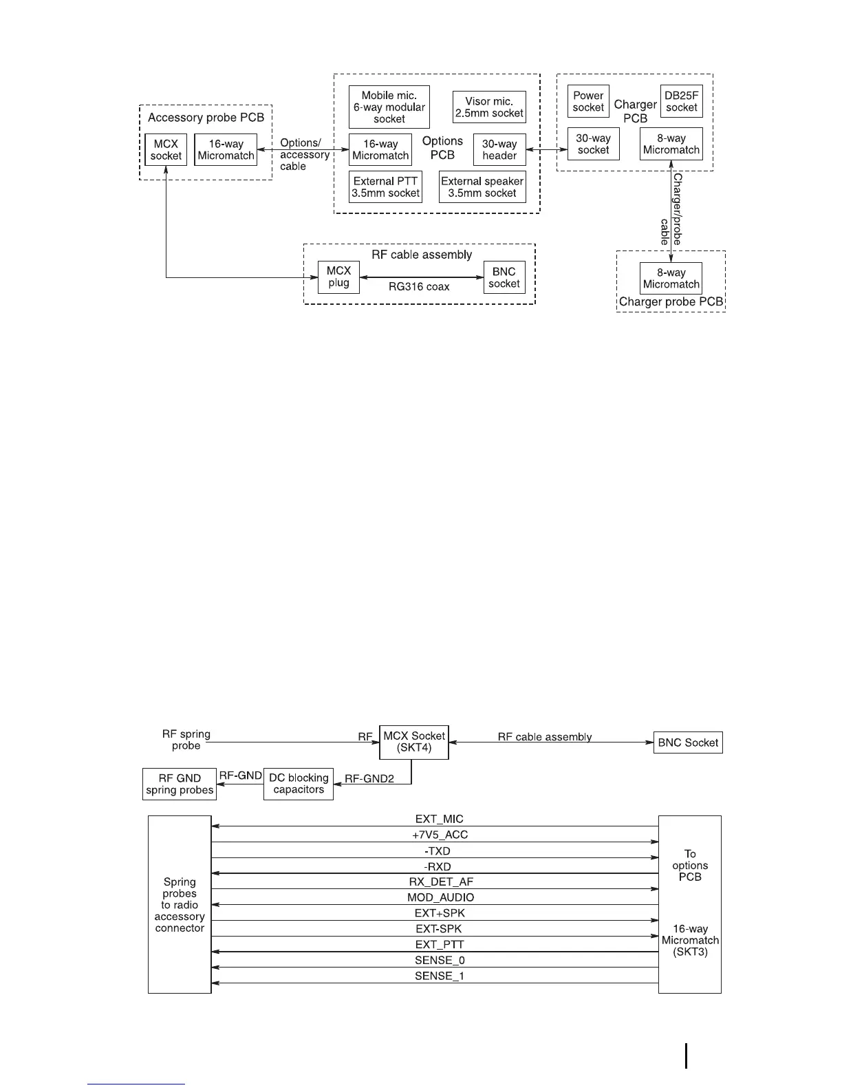
Figure F-9: Vehicle kit interconnection diagram
Vehicle kit circuit descriptions
This section provides an outline of the design
and describes the modular assembly of the
vehicle kit. The vehicle kit contains four PCBs:
■ the accessory probe and charger probe
PCBs, interfacing to the radio and battery;
and
■ the charger and options PCBs, containing
the electronic circuitry.
A block diagram showing how the four PCBs
interconnect and naming the connectors on
each PCB is shown in Figure F-9.
The following subsections and their associated
diagrams expand on the functionality of each
vehicle kit PCB.
Vehicle kit accessory probe PCB
(IPN 220-01506-xx)
This PCB provides the interface to the radio’s
accessory connector. The audio/control
signals connect to the options PCB via a 16-
way MicroMatch ribbon cable. The RF signal
is routed via an MCX connector and coaxial
cable to a BNC connector on the rear of the
vehicle kit. A block diagram of this PCB is
shown in Figure F-10.
Figure F-10: Vehicle kit accessory probe PCB block
diagram