22 Calibrating the Reciter © Tait Electronics Limited February 2007
Equipment ■ Torx 10 screwdriver (to remove the reciter cover)
■ Tuning tool
■ Frequency counter with an accuracy of 50 parts per billion or better. The
equipment must either have its own internal high-accuracy reference or be
locked to an external reference such as the Tait T805.
■ RF attenuator (only required if you are using a PA)
Important: The accuracy of the calibrated TCXO frequency is only
as good as the accuracy of the frequency counter.
Setup
You need direct access to the TCXO circuitry on the reciter RF board. This
involves removing the reciter RF cover.
Important: The reciter contains devices that are susceptible to
damage from static charges. You must handle these devices
according to the recommended ESD precautions.
To adjust the carrier frequency
1. Remove the reciter from the subrack.
2. Remove the M3 Torx screws securing the reciter RF cover to the heatsink
and to the front and rear panels. (The RF side of the reciter can be identified
by the two BNC connectors on that side of the reciter’s rear.) Lift off the
RF cover.
3. Make sure that the equipment is set up and that the Calibration Software is
connected to the reciter.
4. Select the Reciter Calibration tab, and double-click Carrier Freq Offset
Adjustment. The Carrier Freq Offset Adjustment wizard appears.
5. Attach an appropriate load and frequency counter (or a test set) to the exciter
or PA output, and then click Next.
The exciter now begins transmitting on the center frequency of its lock
band. The Wizard displays a message similar to the following:
“Adjust RV1400 to set frequency within 0.1ppm or 48Hz of 485 MHz”
6. Use the tuning tool to adjust the TCXO tuning control (RV1400) so that
the reciter is transmitting exactly on frequency.
The following shows where the tuning control is located on B-band and H-
band reciters:
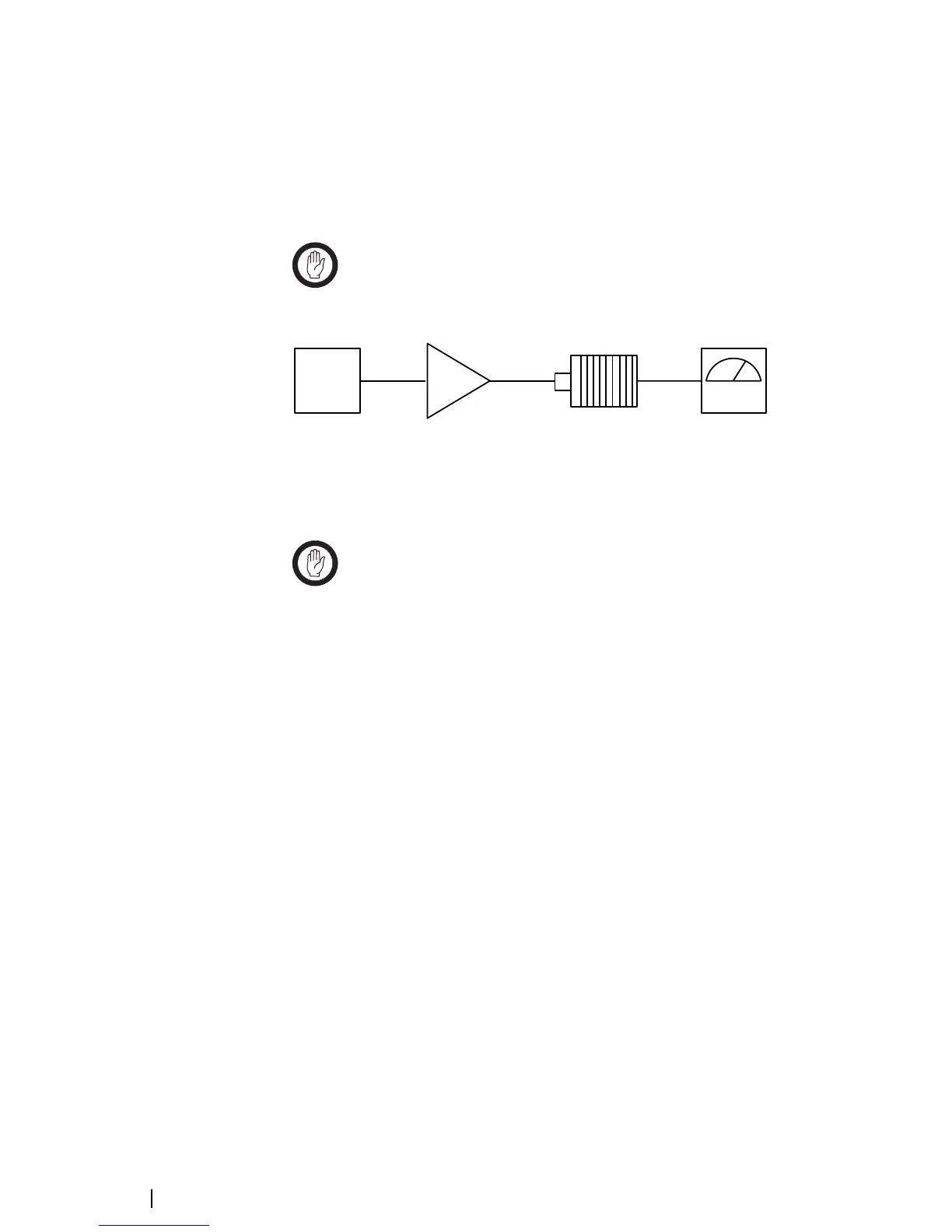
1
2
3
4
1 Reciter 3 RF Attenuator pad (optional)
2 PA (optional) 4 Frequency counter

 Loading...


