TM8100/TM8200 Service Manual Disassembly and Reassembly 151
© Tait Electronics Limited November 2007
7. While pulling upwards on the space frame G at the corner where the
microphone connector is situated, release the clips labelled
B to G in
Figure 5.11 in the order:
B and C, D and E, and then F and G.
To release each clip use a 3/16 inch (5mm) flat-bladed screwdriver to
lever the clip out of its recess. Pulling on the space frame helps release
the clips.
Important When fitting the space frame
G, make sure that the clips
labelled
B to G fully snap into the front panel assembly.
If necessary, use a flat-bladed screwdriver to push down the
clips until they snap into place.
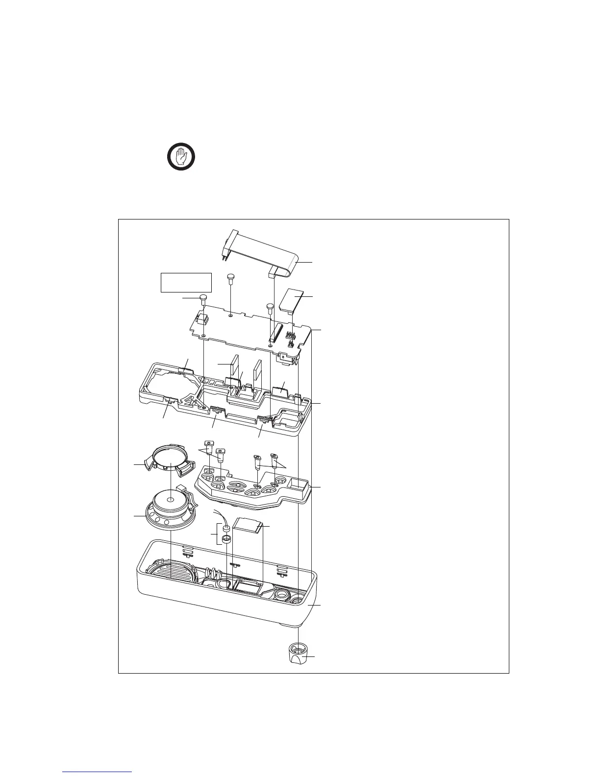
Figure 5.11 Components of the control head (1-, 2- or 3-digit display)
B
control-head loom with female-female
adapter
C
control-head options board (optional)
D
3 x 8 PT screw (x3)
E
control-head board
F
elastomeric strip (x2)
G
space frame
H
speaker clamp
I
speaker
J
short light pipe
1)
long light pipe
1!
keypad
1@
LCD
1#
concealed microphone (optional)
1$
front panel assembly
1%
knob for volume-control potentiometer
x3
B
C
E
F
x2
1#
i
j
1)
1@
h
g
1!
1$
1%
d
Torx T10
5lb·in (0.6N·m)
B
G
E
C
d
F

 Loading...