TM8100/TM8200 Service Manual TMAA04-06 Linking and Interface Cable 581
© Tait Electronics Limited November 2007
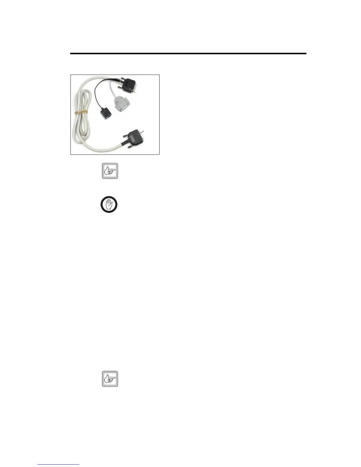
31 TMAA04-06 Linking and Interface Cable
The TMAA04-06 cross-band linking, GPS, and external
interface cable is used to extend the features available with
TM8260 dual radio systems.
Using the cables provided in the TMAA04-06 kit, the radios
can used for the following applications:
■ cross-band repeater
■ connection to a GPS device
■ connection to a vehicle’s ignition signal
■ connection to an external alert device.
Note The cable does not currently support any programmable I/O
actions, or connection to external devices or signals other than
those described in this section.
Important The radio does not meet the IP54 protection standard once
the auxiliary connector rubber bung has been removed and
a crossband linking cable has been installed. Care must be
taken when the radio is being operated in an environment
where there is water, dust or other environmental hazards.
31.1 Cross-band Repeater Operation
The external interface cable in the TMAA04-06 kit is used to connect the
auxiliary ports of two radios, allowing the radio system to be used as a cross-
band repeater. Cross-band repeater mode enables a TM8260 dual radio
system be used as a temporary repeater. Any activity received on one radio
will be automatically transmitted on the other radio, and vice versa.
31.1.1 Installation
1. Remove the rubber bung that covers the auxiliary connector on each
of the radios.
2. Plug an auxiliary connector into the auxiliary port of a radio body.
3. Plug the second auxiliary connector into the auxiliary port of the
other radio body.
Note The cable can be plugged in either way—its orientation has no
impact on radio performance. However, to reduce the cabling
required, orient the cable so the external interface connector and
GPS socket are closest to the device or devices to connect to.
4. Tightly fasten the jackscrew-type locks.
external
interface
connector
RJ45 GPS
socket
primary
auxiliary
connector
secondary
auxiliary
connector

 Loading...