586 TMAA04-06 Linking and Interface Cable TM8100/TM8200 Service Manual
© Tait Electronics Limited November 2007
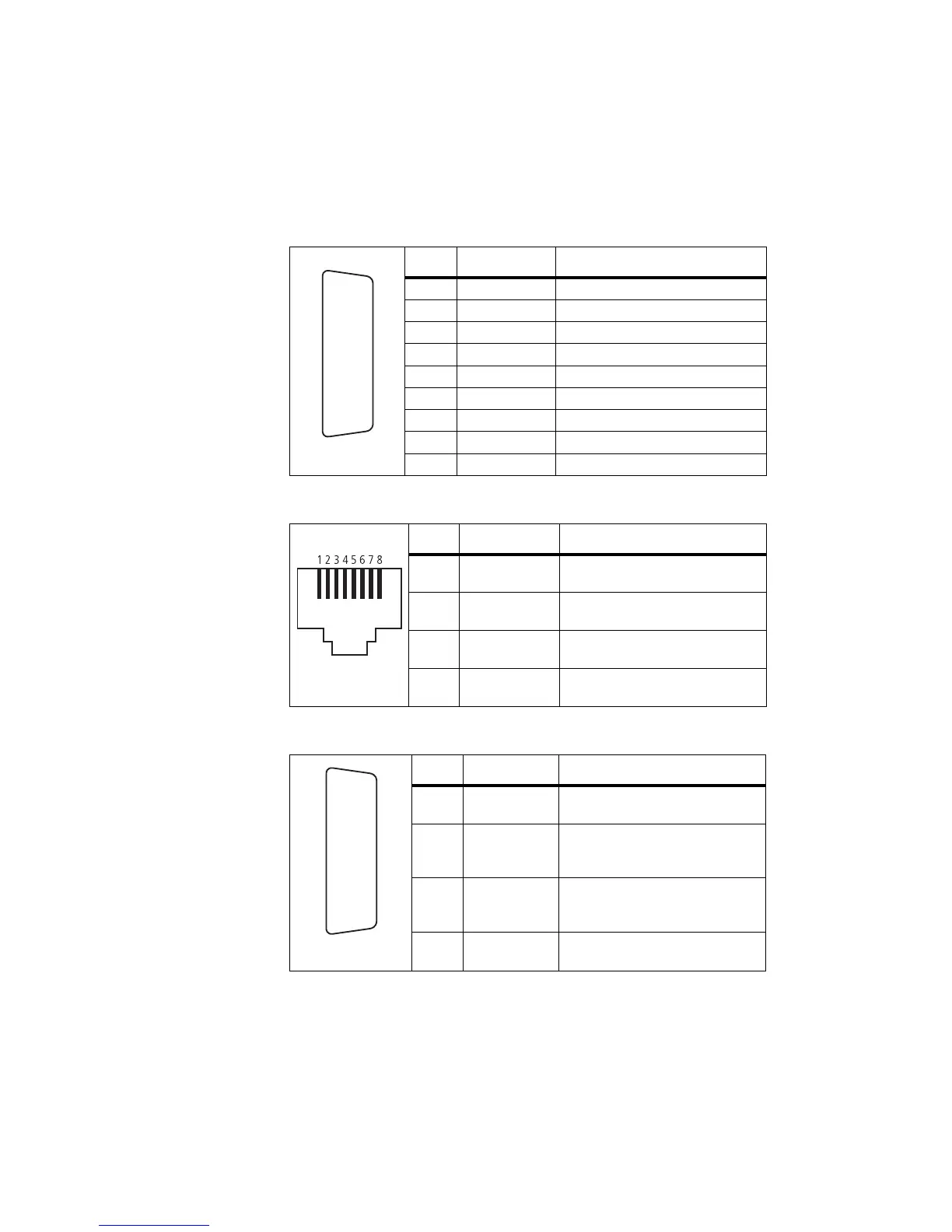
31.5 Interface Specification
The following table and diagram summarizes the signals used for all the
connectors on the cable, and shows the interfaces between the cable and
the radios.
Table 31.7 Auxiliary connectors—pins and signals
Pin Signal name Description
2 AUX_GPIO5 busy (output)
3RXD receive data
4 AUX_GPI3 ignition sense
7 AUD_TAP_IN audio tap input
8 +13V8 power supply to GPS device
9 AUX_GPIO6 external alert
12 AUX_GPI1 PTT (input)
13 AUD_TAP_OUT audio tap output
15 AGND ground
Table 31.8 GPS socket—pins and signals
Pin Signal name Description
1 +13V8 power supply from radio
2 GND ground
3 GND ground
5 GPS_TXD transmit data
Table 31.9 External interface connector—pins and signals
Pin Signal name Description
4 AUX_GPI3 ignition sense
9 AUX_GPIO6 external alert (radio closest to
connector)
10 AUX_GPIO6 external alert (radio furthest from
connector)
15 GND ground
rear view
J
B
C
D
E
F
G
H
I
1)
1!
1@
1#
1$
1%
front view
rear view
J
B
C
D
E
F
G
H
I
1)
1!
1@
1#
1$
1%

 Loading...