TM8100/TM8200 Service Manual Frequency Synthesizer Fault Finding 189
© Tait Electronics Limited November 2007
7. If the lock status is 110, the second LO is out of lock. Go to
“Receiver Fault Finding” on page 247.
8. If the lock status is 111, this implies normal operation. But if the lock
error persists, replace the board and go to “Final Tasks” on page 163.
9.2 Power Supplies
Introduction First check that a power supply is not the cause of the fault. There are four
power supplies for the frequency synthesizer — two are supplied from the
PSU (power supply unit) module and two are produced in the synthesizer
circuitry itself:
■ Task 3: 14VDC (K5 band: 15.5V) supply from SMPS (VCL SUPPLY)
■ Task 4: 6V DC supply from 6V regulator in PSU module (+6V0)
■ Task 5: 5V DC supply following filtering of 6V supply (+5V DEC)
■ Task 6: 3V DC supply from 3V regulator in PSU module (+3V0 AN).
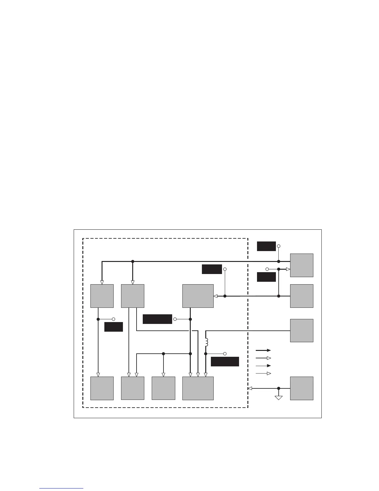
The measurement points for diagnosing faults in the power supplies are
summarized in Figure 9.1.
Figure 9.1 Measurement points for the frequency synthesizer power supply circuitry
PIN 4 OF
Q508

 Loading...