TM8100/TM8200 Installation Guide Installing the Radio 19
© Tait Limited November 2012
3.5 Connecting the Power Cable to the Power Source
This section provides information on connecting the power cable to the
power source.
Power Connector The power connector is the interface to the vehicle battery and an optional
external remote speaker. Connecting a remote speaker is described in
"Connecting a Remote Speaker" on page 21.
Notice This radio is designed to operate from a nominal 12V negative
ground supply and may draw up to 15A of current. The radio will tol-
erate a supply voltage range of 10.8V to 16.0V at the radio.
Selecting the Power
Source
In passenger vehicles, the radio is always connected directly to the battery
using the power cable provided.
Notice Do not connect the radio to the center tap of two 12V batter-
ies! This may result in damage to the radio due to earth loops, in partic-
ular when the negative lead is disconnected from the vehicle battery.
It may also result in overcharging or undercharging of the batteries,
reducing their service life.
In trucks, where direct connection to the battery is often not possible, the
radio can be connected to a suitable terminal inside the fuse box that is
connected directly to the battery.
24V-to-12V
Converter
In vehicles with a supply voltage larger than 16.0V, such as many trucks, it
is essential to provide a 24V-to-12V converter with a minimum rating of
15A for radios >25W and 10A for the 25W radio. This will isolate the radio
from excessive battery voltage and provide the correct DC operating
conditions. Note that most 24V-to-12V converters already fitted are not
rated sufficiently.
Standby Current When connecting the radio to the battery without using the ignition signal
as described on page 25, the standby current is approximately 50mA.
>25W 25W
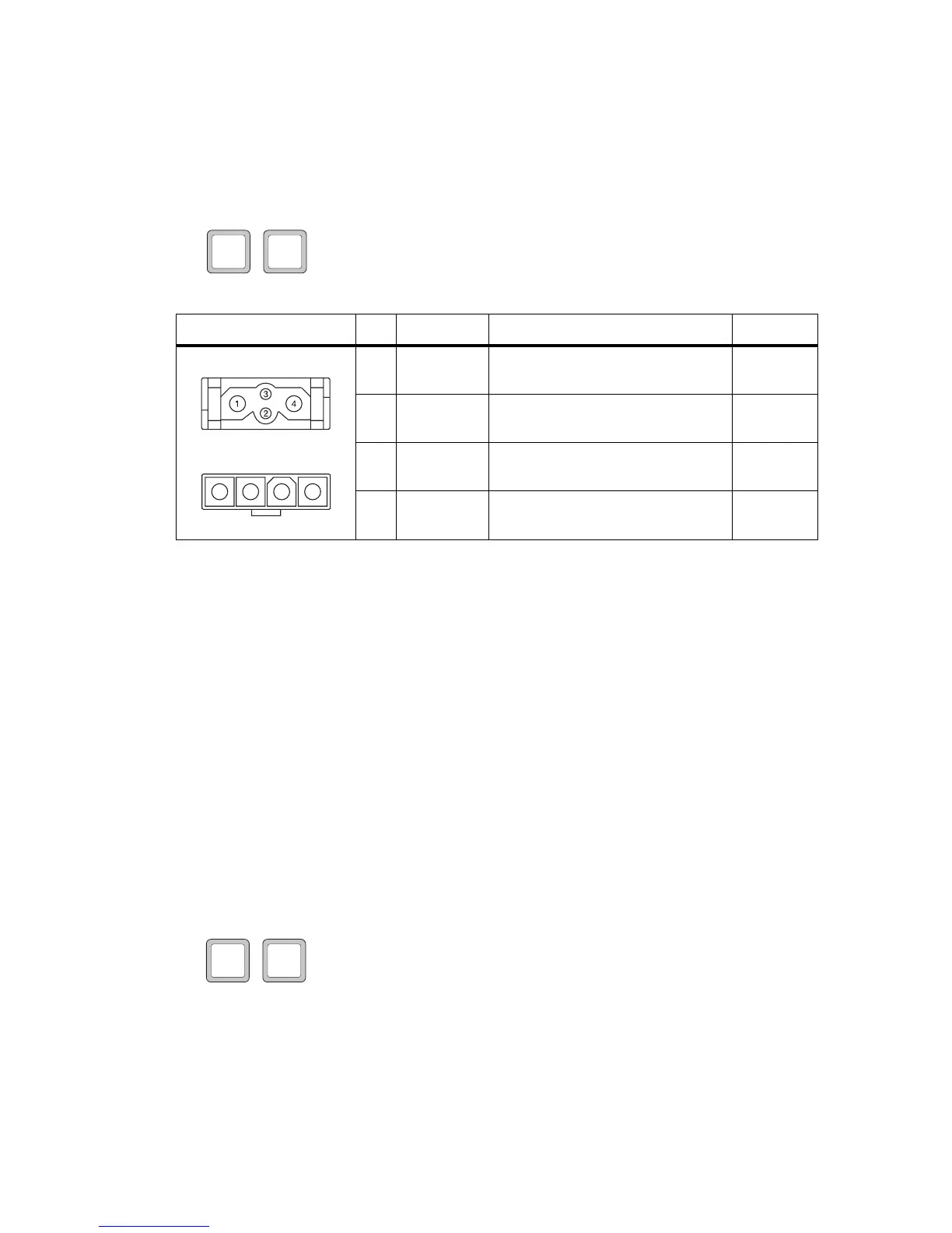
Table 3.1 Power connector (radio) - pins and signals
Pinout Pin Signal name Description Signal type
1 AGND Earth return for radio body power
source
Ground
2 SPK– External speaker output. Balanced load
configuration
Analog
3 SPK+ External speaker output. Balanced load
configuration
Analog
4 13V8 BATT DC power input for radio body and
control head
Power
1 2 3 4
rear view
25W radio
rear view
>25W radio
>25W 25W

 Loading...


