TM8100/TM8200 Installation Guide Installing the Radio 31
© Tait Limited November 2012
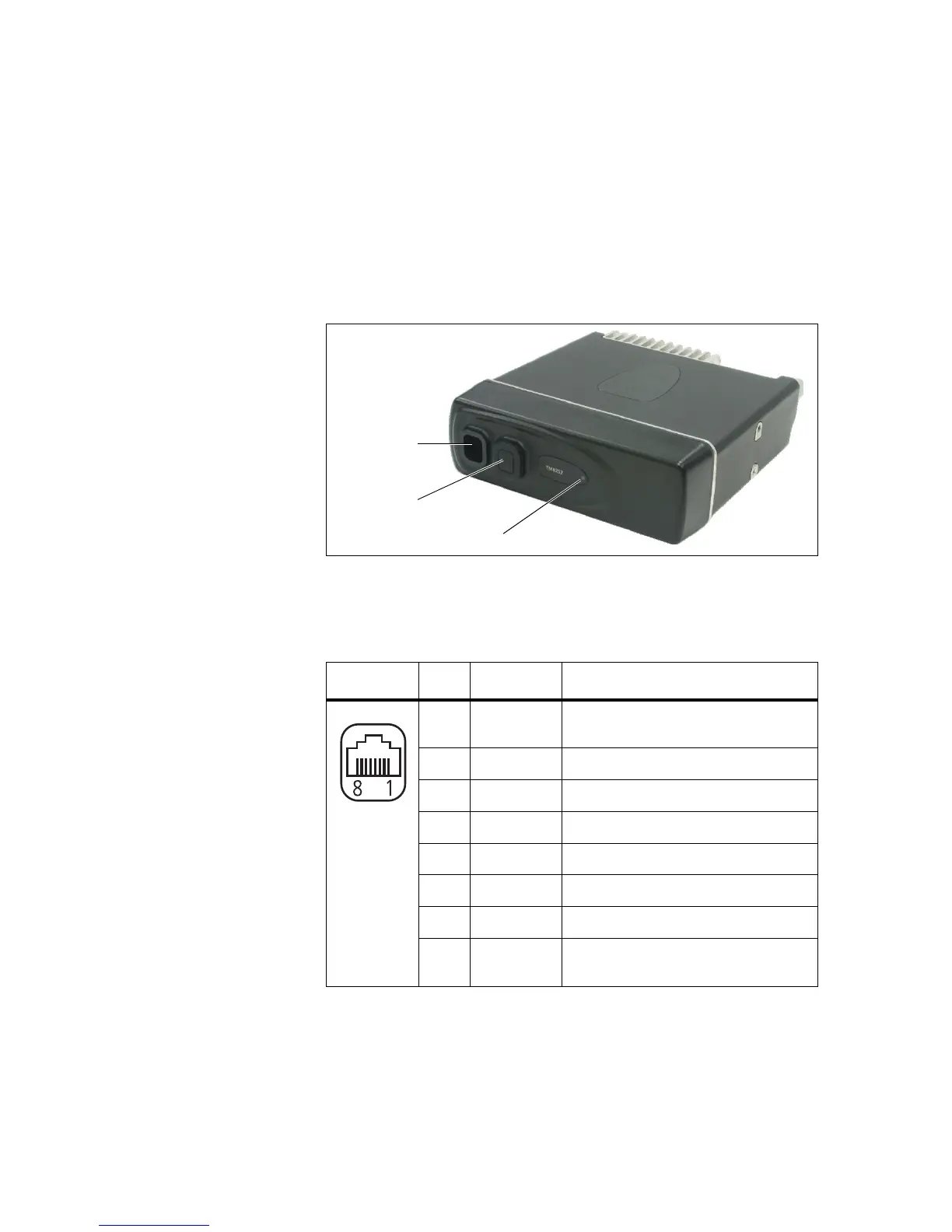
3.12 RJ45 Control Head
The RJ45 control head on the TM8252 telemetry radio has one RJ45
socket installed and a cavity where another RJ45 can be installed. The
control head also has a power on/off LED.
Notice When a connector is not in use, the RJ45 bung for the con-
nector must be installed. This ensures that the control head is sealed
against water, dust and other environmental hazards.
The pin allocations for the RJ45 programming connector are explained in
the following table.
Figure 3.9 TM8252 telemetry radio
Table 3.6 Programming connector for the RJ45 control head - pins and signals
Pinout Pin Signal name Description
1 RX AUD Receive audio output (after volume
control)
2 +13.8V Unswitched 13.8V power supply
3 TXD Asynchronous serial port: transmit data
4 PTT PTT input
5 MIC AUD Microphone audio input
6 AGND Analogue ground
7 RXD Asynchronous serial port: receive data
8 ON/OFF Hardware power on/software power off
input (active low)
RJ45 bung
programming
connector
(bung removed)
on/off LED
front view

 Loading...


