TM8100/TM8200 Installation Guide Installing the Radio 23
© Tait Limited November 2012
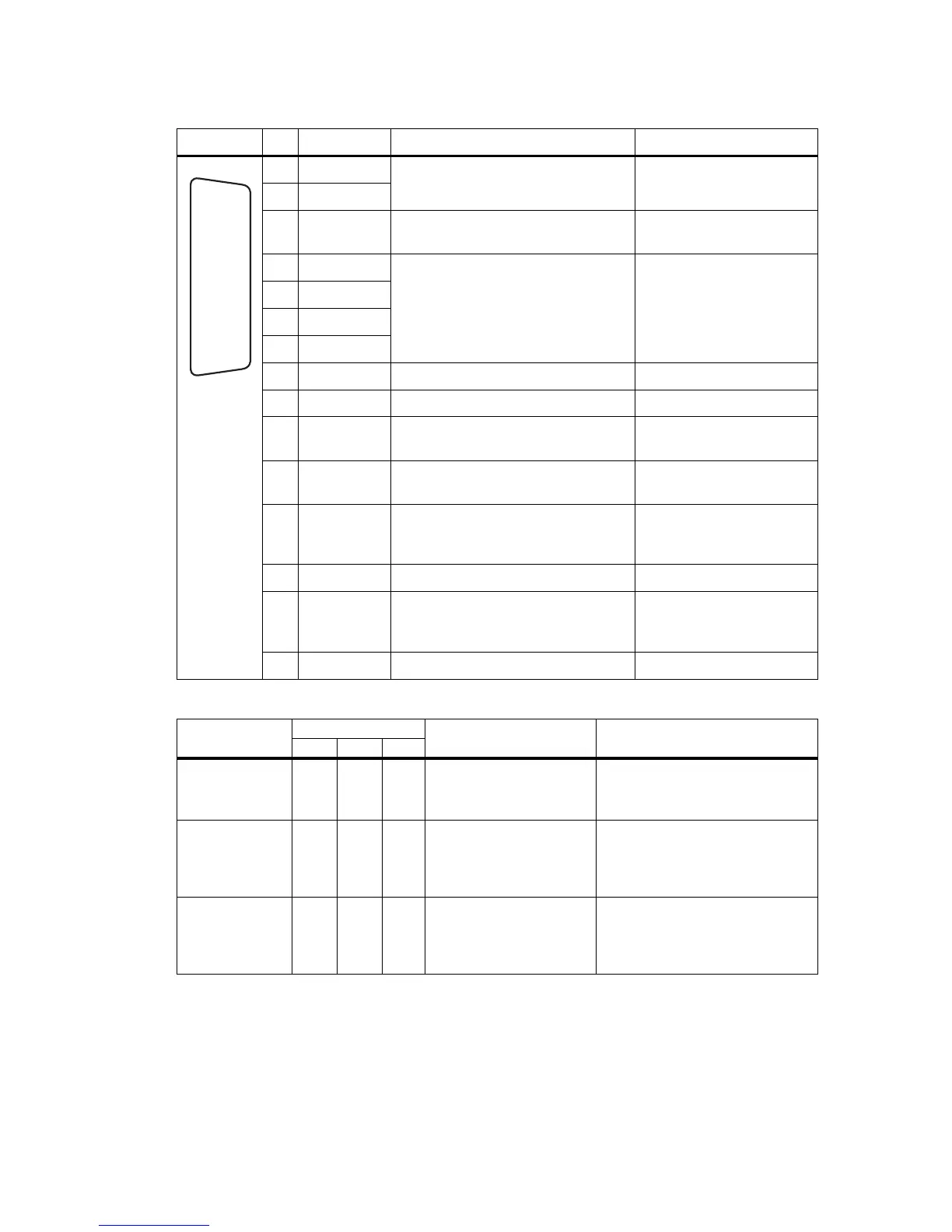
Table 3.2 Auxiliary connector (radio) - pins and signals
Pinout Pin Signal name Description Signal type
12 AUX GPI1 General purpose digital input.
Programmable function
Digital, 3.3V CMOS.
5 AUX GPI2
4 AUX GPI3 General purpose input (ignition sense) 3.3V levels. Protected for
+13.8V (refer to Table 3.3).
10 AUX GPIO4 Programmable function and direction
Pads available to fit a higher power
driver transistor on GPIO4 line
Digital, 3.3V CMOS input;
open collector output with
pullup
2 AUX GPIO5
9 AUX GPIO6
1 AUX GPIO7
11 AUX TXD Asynchronous serial port - Transmit data Digital, 3.3V CMOS
3 AUX RXD Asynchronous serial port - Receive data Digital, 3.3V CMOS
7 AUD TAP IN Programmable tap point into the Rx or
Tx audio chain. DC-coupled
Analog
13 AUD TAP OUT Programmable tap point out of the Rx or
Tx audio chain. DC-coupled
Analog
14 AUX MIC AUD Auxiliary microphone input.
Electret microphone biasing provided.
Dynamic microphones are not supported
Analog
6 RSSI Analog RSSI output Analog
8 +13V8 SW Switched 13.8V supply. Supply is
switched off when radio body is
switched off
Power
15 AGND Analog ground Ground
rear view
J
B
C
D
E
F
G
H
I
1)
1!
1@
1#
1$
1%
Table 3.3 Auxiliary connector - input levels
Parameter
Voltage
1
Test method and conditions Comments
min. max. units
Input low level:
All inputs
AUX_GPI2
0.7
V
s
–4
V
V
No hardware links fitted
2
.
LK3 fitted.
Includes AUX_GPI3 with LK1/2 fitted.
Configured as emergency power sense
input.
Input high level:
All inputs
AUX_GPI2
AUX_GPI3
1.7
V
s
–1.5
2.6
V
V
V
No hardware links fitted
2
.
LK3 fitted.
LK1 and/or 2 fitted.
Configured as emergency power sense
input.
Configured as power sense input.
Safe DC input limits:
AUX_GPI1-3
AUX_GPIO4-7
AUX_RXD
AUX_TXD
3
–0.5
–0.5
–25V
–10
V
s
+0.5
V
s
+0.5
V
s
+0.5
V
s
+0.5
V
V
V
V
The input current must not exceed
±50mA. This is the rating of the
clamping diodes.
1. The radio will tolerate a supply voltage range of 10.8V to 16.0V at the radio.
2. For more information on hardware links refer to Table 3.4 on page 24 and to the service manual.
3. This output is protected against accidental input to the limits specified.

 Loading...


