TM8100/TM8200 Installation Guide Installing the Radio 25
© Tait Limited November 2012
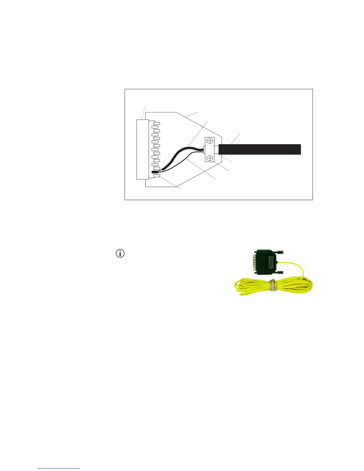
Shielding
If the auxiliary cable is longer than 4 feet (1m) it is recommended that the
cable and connector backshell are shielded. Figure 3.5 shows the
recommended shielding arrangement. The earth braid wire (bare copper)
and aluminum foil should only be earthed at the radio end of the cable.
Ignition Signal The ignition signal can be used to power up and power down the radio.
This will turn the radio off when the ignition key is off to avoid flattening
the battery, and will turn the radio on or return to its previous state (as
programmed) when the ignition key is on.
A TMAA04-05 ignition sense kit is
available. The kit comprises a mating
plug for the radio’s auxiliary connector
and a 13 foot (4m) length of cable to
connect to the vehicle’s ignition signal.
Refer to the installation instructions
supplied in the kit for full details.
Notice The AUX GPI3 line must
be programmed to ‘Power Sense (Ignition)’ and active to ‘High’.
For more information, refer to the online help of the programming
application.
■ Connect the ignition signal to pin 4 (AUX GPI3) of the auxiliary
connector.
Notice The logic thresholds for AUX GPI3 are based on 3V3 levels.
However, AUX GPI3 can be connected directly to a +13.8V
ignition signal (for input levels, refer to Table 3.3 on page 23).
Figure 3.5 Auxiliary cable and connector shielding
metal D-range shroud in
contact with backshell
metal backshell
signal earth wire
aluminum foil
cable insulation
metal cable clamp
earth braid wire
analog ground pin

 Loading...


