Tally Dascom DL-210 User Guide V1.3
53
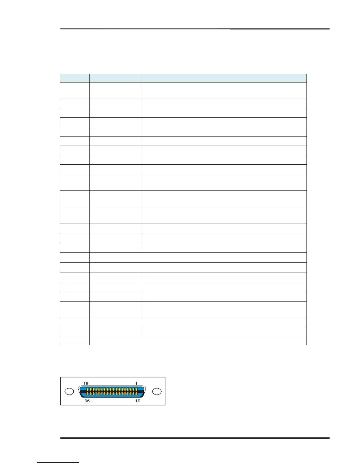
6.6 Parallel interface
Parallel interface pin assignment
Parallel interface with 36 pin CENTRONICS socket.
Strobe Signal; Data latch pulse, latch the data to the printer
at the rising edge of the negative pulse.
ACK Signal; Printer response signal, indicates that the
printer has received a Data byte.
Busy Signal; The printer is busy; High level indicates that
the printer can’t receive data.
PE Signal; Paper end signal; High level indicates that the
printer is out of paper.
Frame Ground, separated from logic ground.
Printer error signal. Low level indicates that an error occurs
in the printer. It will come with paper end.
Remarks:
H indicates that signal comes from Host computer; P indicates that signal comes from Printer.
Parallel interface connector diagram