5-2
USER INTERFACE
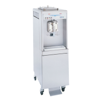
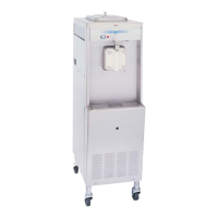
Models 60 and 62
User Interface
5
Symbol Definitions
To better communicate in the international arena, many
of our operator switches and buttons use symbols to
indicate their functions. Your Taylor machine is designed
with these international symbols.
The following chart identifies the symbol definitions:
= ON/AUTO
= OFF
= MIX Button
= WASH
= MIX LOW
= MIX OUT
= HEAT MODE
= FILL Button
= RINSE Button
Control Switch
The center position is OFF. The left position is WASH,
which activates the beater motor only. The right position
is AUTO. It activates the beater motor and the
refrigeration system. To activate the refrigeration system,
raise the draw arm momentarily.
Dial Light
A red dial light is on the right side of the control switch.
When the control switch is in the AUTO position, this light
will come on, indicating that the refrigeration system is
operable.
Indicator Light—MIX LOW
The MIX LOW indicator light is on the front of the
machine directly above the flavor selector switch. When
the light flashes, it indicates that the mix hopper has a
low supply of mix and should be refilled as soon as
possible. If mix is not added, a starved freezing cylinder
will cause damage to the beater, blades, and driveshaft.
Indicator Light—MIX OUT
A MIX OUT indicator light is on the front of the machine
directly above the control switch. When the light is on, the
machine will shut down to prevent a starved freezing
cylinder.
Reset Mechanism
CAUTION! DO NOT use metal objects to press
the RESET button. Failure to follow this instruction may
result in electrocution.
The reset protects the beater motor from overloading. If
an overload occurs, the reset mechanism will trip. To
properly reset the freezer, set the control switch to OFF.
Lift up the right upper-side panel and press the RESET
button firmly. Turn the control switch to WASH and
observe the freezer’s performance. Return the control
switch to the AUTO position to resume normal operation.
If the reset mechanism should trip again, contact your
Taylor distributor to resolve the problem.
Figure 5-2