31
2.4
Rear Panel Connectors
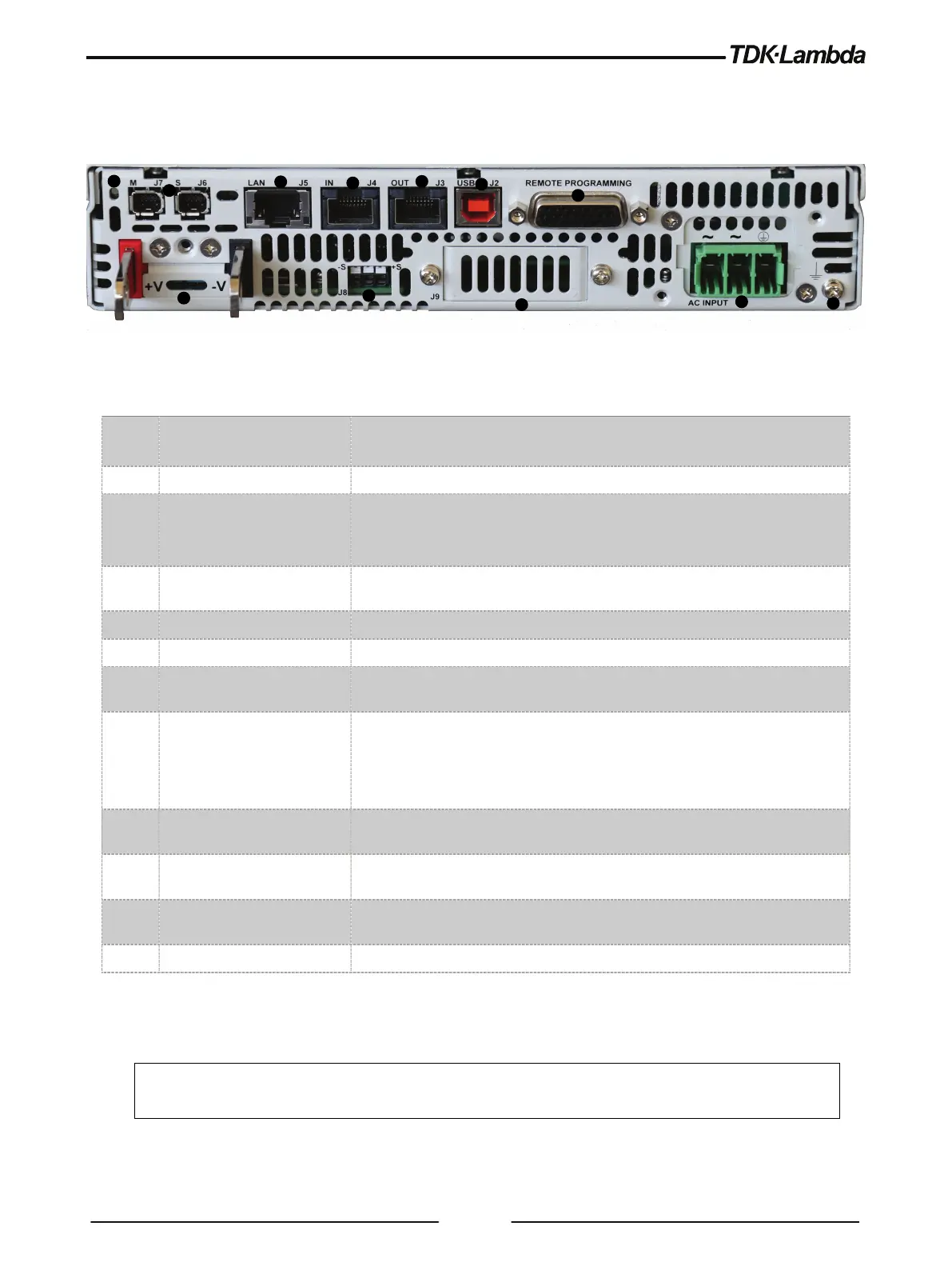
Refer to Figure 2-3 and Table 2-3 for description of the Rear Panel connectors.
Figure 2-3: Rear Panel Connectors and Controls
1 AC Input Connector Connector type:
1-Phase: PC 3/ 4-G-7,62 PHOENIX CONTACT.
2 Ground Screw Functional Ground connection M3x8 Screw
3 DC output Bus bars /
Connector
Bus bars for 10V to 100V models.
150V to 600V Connector type:
GIC 2.5/4-G-7,62 PHOENIX CONTACT
4 Remote sense connector
Connector for remote sensing connections. Connect to the load for
regulation of the load voltage and compensation of load wire drop.
5 Reset button Set default Power Supply settings.
6 Paralleling Connectors Master/Slave connectors, mini I/O type.
7 LAN Connector +
LAN interface connector, RJ-45 type + LXI indicators. Connector type: UDE
8 Serial In connector
RJ-45 type connector, used for connecting power supplies to RS232 or
RS485 port of a computer for remote control purposes. When using several
power supplies in a power system, the first unit Serial-In is connected to
the computer and the remaining units are chained, Remote-Out to Remote-
In. Connector type: Molex 95540-2881.
9 Serial Out connector RJ-45 type connector, used for chaining power supplies to/from a serial
communication bus. Connector type: Molex 95540-2881.
10 USB Connector
USB interface connector, type B. Connector type: SAMTEC P/N: USBR-B-S-
F-O-TH.
11
Isolated control and signals
(J1)
Isolated analog Control and monitoring signals, isolated from the output
potential. Connector type: WE P/N: 618026325223.
12 Optional Interface Position for optional communication interface.
Table 2-3: Rear Panel Connectors and Controls
CAUTION
To prevent ground loops and to maintain the isolation of the power supply when programming from
J1, use an ungrounded programming source.