20
The alarm output port should not be connected to high power load directly (It shall be less than
1A) to avoid high current which may result in relay damage. Use the co contactor to realize the
connection between the alarm output port and the load.
3. How to connect PTZ decoder
a. Ensure the decoder has the same grounding with DVR, otherwise you may not control the PTZ.
Shielded twisted wire is recommended and the shielded layer is used to connect to the grounding.
b. Avoid high voltage. Ensure proper wiring and some thunder protection measures.
c. For too long signal wires, 120Ω should be parallel connected between A, B lines on the far end
to reduce reflection and guarantee the signal quality.
d. “485 A, B” of DVR cannot parallel connect with “485 port” of other device.
e. The voltage between of A,B lines of the decoder should be less than 5v.
4. Make sure the front-end device has soundly earthed.
Improper grounding may result in chip damage.
3.7.1 Alarm Output Port
Provide external power to external alarm device.
To avoid overloading, read the following relay parameters sheet carefully.
RS485 A/B cable is for the A/B cable of the PTZ decoder.
T+,T‐,R+,R‐ are four-wire double duplex RS485 port.
T+ T-: output wire,
R+ R-: input wire
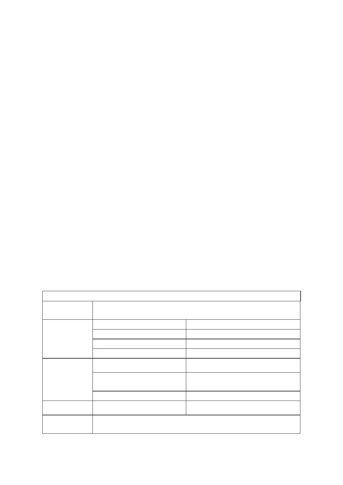
Relay Specification
Model:
JRC-27F
Material of the
touch
Silver
Rating
( Resistance
Load)
Rated switch capacity 30VDC 2A, 125VAC 1A
Maximum switch power 125VA 160W
Maximum switch voltage 250VAC, 220VDC
Maximum switch currency 1A
Insulation Between touches with same
polarity
1000VAC 1minute
Between touches with different
polarity
1000VAC 1minute
Between touch and winding 1000VAC 1minute
Surge voltage
Between touches with same
polarity
1500V (10×160us)
Length of open
time
3ms max