Installation / Operation Manual
4728
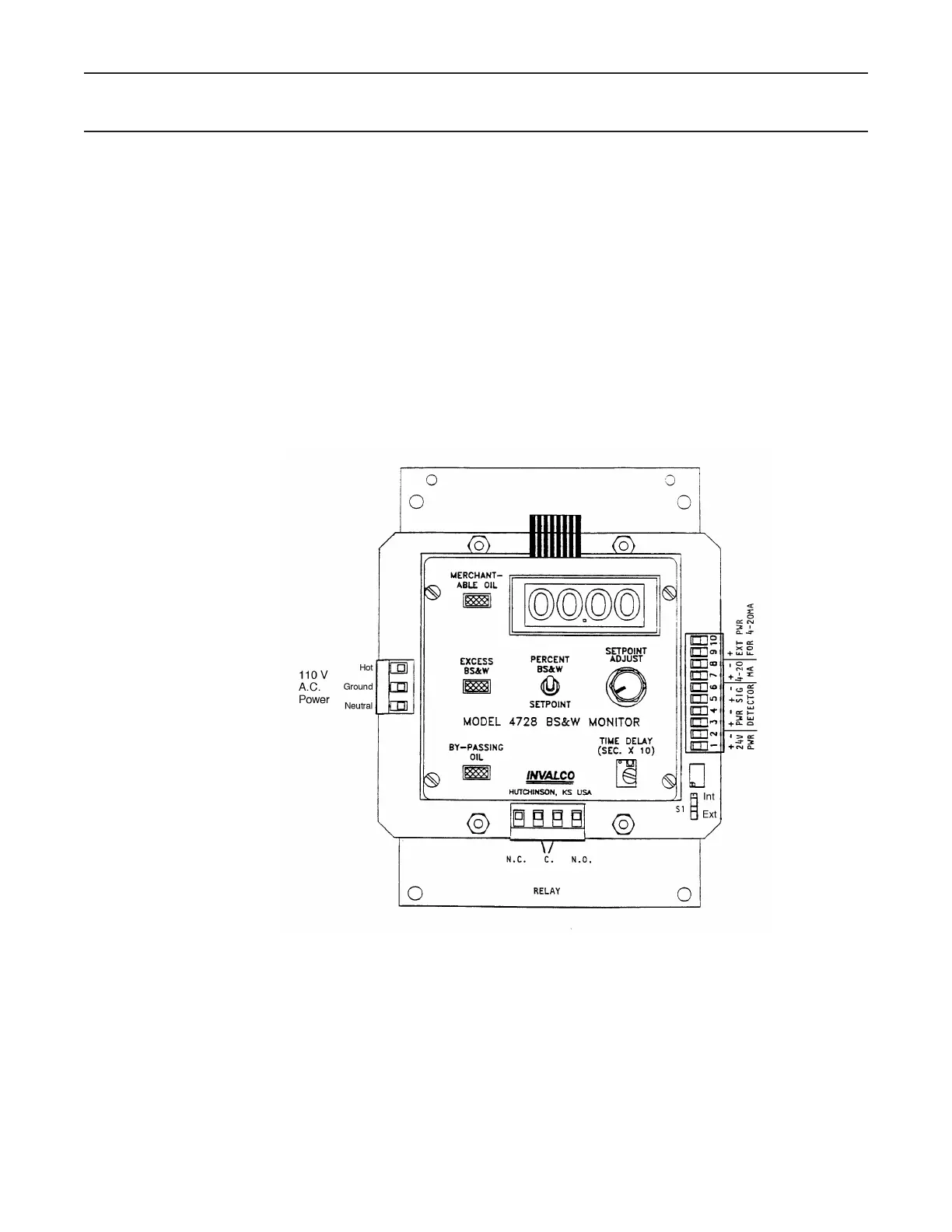
The functions and locations of these three blocks on the P.C. card are as follows:
(a) Left side - 110 V AC power input
(b) Bottom - Relay contacts
(c) Right side - Detector card connections, 4-20 mA hook-ups and 24 V DC power input
for DC operation of the 4728.
Note: Switch S1 which is located at the lower right of the P.C. card. The position of this
switch determines whether the 4-20 mA output is to be internally powered from the
4728, or externally powered from an outside source. Care must be taken to be sure
this switch is in its proper position BEFORE an external 4-20 mA loop power source
is connected. Failure to have the switch in the proper position may cause component
The function and operation of all other controls on the 4728 are as described in the
manual.