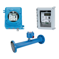
This document is an installation and operation manual for the TechnipFMC Water Cut Monitor, comprising the 4528 Detector, CX-645 Probe, and CSA Approved 4728 Monitor. The system is designed for continuous on-line monitoring of percent water in crude oil.
Function Description
The Water Cut Monitor system measures changes in the product stream capacitance. The dielectric constant (Dk) of the product stream changes dramatically as water content varies. This change in capacitance is accurately measured and correlated to percent water by calibration against "shake out" data. The Model 4728 displays the percent water on a digital indicator, and indicator status lights continuously display the conditions measured by the system. Alarm relays and a 4-20 mA output can be used to connect the system to other supervisory or control elements.
The 4528 Detector mounts in an explosion-proof conduit on the capacitance probe. It converts water changes in the oil flowing through the probe to an output voltage that varies with the water. The CX-645 Probe is constructed of two concentric tubes with wetted and internal surfaces coated with a fused epoxy powder. The inner tube is insulated from the outer tube by PTFE (polytetrafluoroethylene) spacers and is electrically connected to a terminal within the sensor housing. Trimmer rods can be fitted to the internal element spacers to adjust the base capacitance.
Important Technical Specifications
Model 4728 S&W Monitor:
- Input Power: 115 VAC +/- 15%, 50/60 Hz, 2 watts; 220 VAC (Optional); 14-28 Volts DC @ 130 mA.
- S&W Range: 0-5%, 0-10%, or 0-20%.
- S&W Alarm Setpoint: 0-100% of S&W Range.
- Input Signal: 0-5V DC from 4528 Detector.
- Indicators: S&W / Setpoint LCD, Merchantable Oil LED (Green), Excess S&W LED (Red), Bypassing Oil LED (Yellow).
- Outputs: 4-20 mA analog.
- Relays: SPDT Relay, 10 Amp 250 VAC; 1/2 Hp 250 VAC, 13A 120 VAC resistive; 1/3 Hp 120 VAC, 10 A 30V DC resistive.
- Time Delay: 0-90 seconds adjustable in 10-second steps. Off delay is approximately 10% of on delay time.
- Temperature Range: -20°F to 160°F (-29°C to 71°C).
- Enclosure: NEMA 4X, Fiberglass, water resistant; NEMA 7, Explosion Proof.
- Part Numbers: Model 4728 Monitor/WP Housing (81001114), Model 4728 Monitor/EXP Housing (81001115).
Model 4528 Detector:
- Output: 0-5 volts, regardless of the range (0-5%, 0-10%, 0-20%).
- Part Number: 81001164.
- Types A, B, and C: Type "C" Detector includes a Fail-safe Switch to tailor output requirements.
- Fail-safe Switch Positions: Low Fail-Safe (default) and High Fail-Safe.
- Detector Output (SIG+ and SIG- Terminals):
- Overrange: 8 to 9 Volts (both Low and High Fail-Safe).
- Underrange: 0 Volts (both Low and High Fail-Safe).
- Open Probe: 0 Volts (both Low and High Fail-Safe).
- Shorted Probe: 8 to 9 Volts (both Low and High Fail-Safe).
- 4-20mA Module (4528-X A): Internally powered, maximum loop resistance 250 ohms. Not designed for use with Model 4728 Readout Unit.
CX-645 Probe:
- Connections Available: Flanged, Grooved, Screwed.
- Vent/Drain: 1-1/4" NPT.
- Pipe Sizes Available: 2" (Dim. "A" 17"), 3", 4", 6", 8" (Dim. "A" 32").
- Catalog Model Numbers (Examples): CX-645-200-BGP (81001190), CX-645-200-BFP (81001191), CX-645-230-BGP (81001192), CX-645-260-BGP (81001193).
- Field Conversion kit available to modify Model CX-201 Probes to CX-645 configuration (Stock No. 49020402).
Usage Features
4728 Monitor:
- Percent Water Set Point: The digital indicator displays percent BS&W. The setpoint (BS&W Limit) can be observed and changed using the percent BS&W/Setpoint switch and the setpoint adjust knob.
- Time Delay: Adjustable from 0-90 seconds in 10-second steps, controlling the delay between excess BS&W indication and relay transfer.
- Analog Output (4-20 mA): Corresponds to 0-5%, 0-10%, or 0-20% depending on unit range. The 4 mA point is adjustable with the zero control, while the 20 mA point is factory preset.
- Loop Switch: Determines whether the 4-20 mA loop is self-powered (internal mode, max 600 ohms resistance) or powered by a remote supply (external mode, max 40 volts, 3-wire circuit). Caution: Ensure the loop switch is in the proper position before connecting an external power source to prevent circuit damage and voiding the warranty.
Typical Applications:
- Percent Water Indication: The Indicating Unit provides local or remote percent water readings.
- Percent Water Indication and Set-Point Control: The adjustable alarm can operate a diverter valve if water content exceeds a preset percentage.
- Percent Water Indication and Pneumatic Control: An analog-to-air converter can provide a 3-15 psi pneumatic output signal proportional to water content.
- Percent Water Recording: The Indicating Unit provides local readings and an analog output signal for recorders, meters, computer inputs, or other DC input devices.
Installation Hints:
- Always install the probe upstream of a dump valve when mounted on an oil line coming off a treater or separator to prevent erratic readings from gas bubbles.
- Vertical flow through the probe is recommended (either up or down) to prevent water buildup in low spots.
- Locate the oil sample removal point as close as possible to the probe, preferably downstream and below the probe in elevation, to ensure accurate water measurement.
- L.A.C.T. Systems should have back pressure valves on both "good" and "bad" oil lines for constant pressure on the oil in the probe.
Maintenance Features
Calibration (4528 Detector 0-5 VDC Output):
- Connect power and probe detector chassis/indicator unit.
- Stabilize oil flow through the probe.
- Take a grindout of water in oil (preferably less than 1% water).
- Apply power to the Model 4728 indicator unit.
- 4528 Detector Calibration:
- Set probe/ref. switch to probe position.
- Set DC voltmeter on 0-10 volt scale.
- Adjust fine zero (ZERO F) clockwise until fully CW (clicking sound), then back counter-clockwise approximately 10 turns.
- Adjust coarse zero (ZERO C) counter-clockwise until fully CCW (clicking sound), then clockwise until the reading is at or near the grindout value (do not tune through zero, always approach from CW).
- Adjust fine zero for complete agreement with the grindout value.
- Move Probe/Ref. switch to Ref. position.
- Adjust span control to make the reading 5.00 higher than the grindout.
- For 10% Detector, adjust COARSE/FINE tuning to read 1/2 the water cut.
- For 20% Detector, adjust COARSE/FINE tuning to read 1/4 the water cut.
- Remove voltmeter and move Probe/Ref. switch to probe position.
- 4728 Readout Unit Calibration:
- Pull and hold the S&W/Set Point Switch down. Turn the set point adjust knob to obtain the desired divert reading. Release switch.
- Turn the time delay switch to set the output relay actuation time after the excess S&W light comes on.
Calibration (4528-X A with 4-20mA Module):
This procedure involves setting the detector with 0-5 volts, then adjusting the 4-20 mA output to match the water content. The 4-20 mA loop is internally powered from the 4528-A. The 4 mA pot adjusting screw is accessible through a hole for adjustment without removing the face plate (mid-year 2000 onwards).
Troubleshooting:
- Fluctuating Readings: Possible causes include gas in oil (downstream of dump valve), restricted suction to charge pump (cavitation/gas break out), or a loose inner electrode probe.
- Output Gradually Increases: Often caused by buildup (paraffin, film from chemicals) in the probe. Check resistance and capacitance from the probe stud to ground. Resistance should theoretically be infinite, but good results are achievable down to 500,000 ohms. Empty probe capacitance should be no more than 95 pf. Full probe with dry oil should measure between 135 pf to 200 pf. If probe insulators are contaminated (voltage reading >.25 volts), they should be changed.
- No Reading/LED Lights on 4728: No power applied or fuse blown.
- No Output from 4528 Detector: No power or probe wire not attached to probe stud, or a bad 4528 Detector Card.
- Rapidly Varying 4-20 mA Output: Heavy electrical static in the air being picked up by 4-20 mA wiring. Use shielded twisted pair wire, grounding the shield at the 4728 Unit only.
Recommended Spare Parts:
- 1/2 amp slo-blo fuses p/n 68108327.
- Relay p/n 36017183.
- Detector (0-5% p/n 81001164, 0-10% p/n 81001160, 0-20% p/n 81001161, 0-5% (4-20mA) p/n 81001295, 0-20% p/n 81001296).