2
st
Edition, April 22
th
, 2008
P2002 Sierra
MAINTEN ANC E MAN UAL
SECTION E
SYSTEMS
pag
.
E-3
the instrument panel and fed directly from the fuel manifold “X” connection (11)
by a firewall pass through hose.
Figure E-1 illustrates the components of the fuel system.
Inside piping from topmost point of each fuel tank connects to fuel vents (4) lo-
cated on wing tip trailing edge.
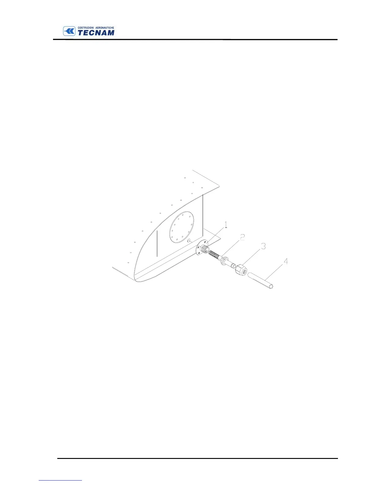
Fuel outlet is located at the lowest point of the inboard sidewall of each fuel tank
and is equipped with a standard mesh filter (2) (see Fig. E-2). To carry out peri-
odic cleaning of mesh filter (2), it is necessary to remove the hose (4) after releas-
ing nut (3).
F
IGURE
E-2
T
ANK OUTLET AND FILTER
Potential fuel tank leaks can be readily detected by the visible fuel traces. Re-
pairs can eventually be made, only if cracks are small and using specific glue
type (1422-B2 DMS 2082), after emptying tank and thoroughly and repeatedly
rinsing the area with water.
Periodically check fuel tank vents to ensure that their openings are unobstructed;
repeat inspection more frequently if operating in dusty conditions. It is recom-
mended, for inspection, to use a small rubber hose to blow through the vent to
clear possible obstructions.
Fuel system servicing includes also the periodic inspection of the Gascolator
drain-cup (6e) and filter (6c) in addition to the inspection of the entire fuel line.
 Loading...