27
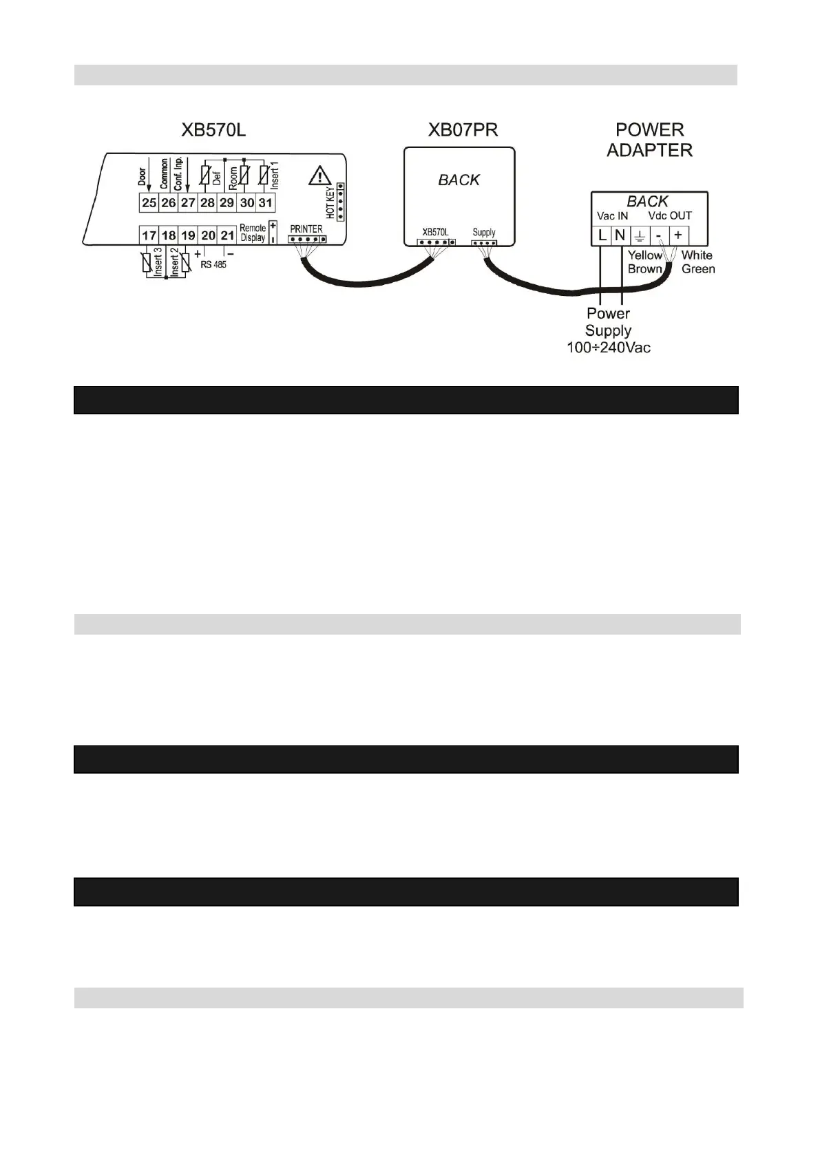
19.3 CONNECTION TO THE XB570L – XB07PR
20. Electrical connections
The instruments are provided with screw terminal block to connect cables with a cross section up to 2,5
mm2 for the digital and analogue inputs. Relays and power supply have a Fast on connection (6,3mm).
Heat resistant cables have to be used. Before connecting cables make sure the power supply complies
with the instrument’s requirements. Separate the probe cables from the power supply cables, from the
outputs and the power connections. Do not exceed the maximum current allowed on each relay, in case
of heavier loads use a suitable external relay.
N.B. Maximum current allowed for all the loads is 20A.
20.1 PROBE CONNECTIONS
The probes shall be mounted with the bulb upwards to prevent damages due to casual liquid infiltration. It
is recommended to place the thermostat probe away from air streams to correctly measure the average
room temperature.
21. TTL Serial line
The TTL connector allows, by means of the external module TTL/RS485, to connect the unit to a network
line ModBUS-RTU compatible as the DIXEL monitoring system XJ500 (Version 3.0).
The same TTL connector is used to upload and download the parameter list of the “HOT KEY“.
22. Use of the programming “HOT KEY”
The Wing units can UPLOAD or DOWNLOAD the parameter list from its own E2 internal memory to the
“Hot Key” and vice-versa.
22.1 DOWNLOAD (FROM THE “HOT KEY” TO THE INSTRUMENT)
1. Turn OFF the instrument by means of the ON/OFF key, remove the TTL serial cable if present, insert
the “Hot Key” and then turn the Wing ON.