Table 1: Front-panel connectors
Connector Description
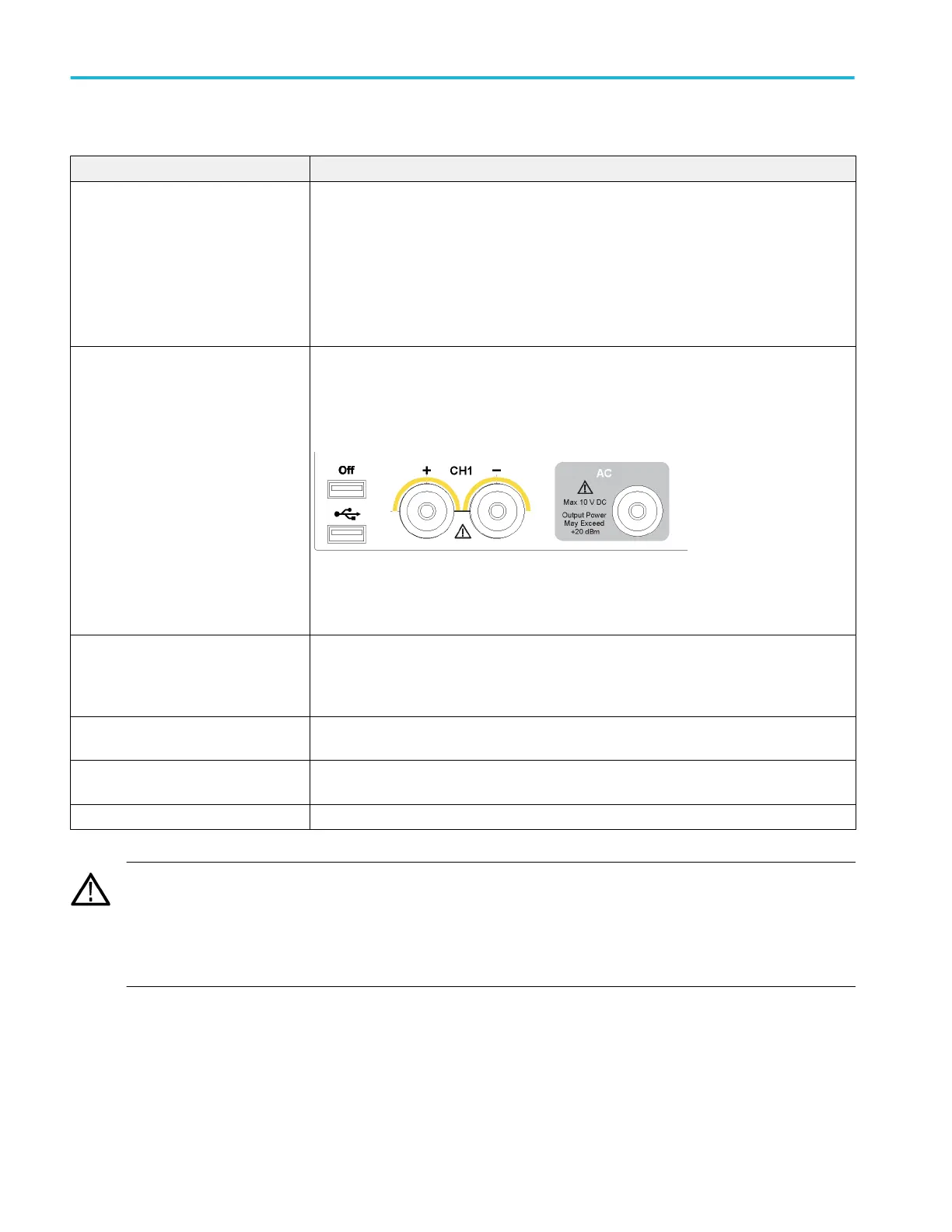
Analog outputs (+ and –)
AWG70001A – CH1
AWG70002A – CH1 and CH2
These connectors supply analog signals.
The channel LEDs light to indicate when the channel is enabled and the output is electrically
connected. The LED color matches the user defined waveform color.
The output connector utilizes the Planar Crown
®
Universal Connector System providing you
the ability to easily replace a damaged connector.
You also have the ability to use a variety of different types of connectors.
The AWG70000A series products ship with SMA type adapters installed.
AC output (Option AC, AWG70001A
only)
This connector supplies a single-ended analog signal. The AC output provides for additional
amplification and attenuation of the output signal.
The AC output LED lights to indicate when the AC output is enabled and the output is
electrically connected. The LED color matches the user defined waveform color.
The output connector utilizes the Planar Crown
®
Universal Connector System providing you
the ability to easily replace a damaged connector.
You also have the ability to use a variety of different types of connectors.
Marker outputs
AWG70001A – CH1 Markers
AWG70002A – CH1 and CH2 Markers
These SMA type connectors supply marker signals, two markers for each channel.
The marker LEDs light when the corresponding channel is enabled and the outputs are
electrically connected. Marker LEDs are always white.
USB Two USB connectors. When OFF is lighted, the front USB connectors have been disabled from
the Utilities > Preferences menu.
Removable hard disk drive (HDD) The HDD contains the operating system, product software and all user data. By removing the
HDD, user information such as setup files and waveform data is removed from the instrument.
Chassis ground Banana type ground connection.
CAUTION. Always turn off the signal outputs when you connect or disconnect cables to/from the signal output connectors. Use
the All outputs off button (either the front-panel button or the screen button) to quickly disable the Analog, Marker, and Flag
outputs. When the All outputs off is enabled, the output connectors are electrically disconnected from the instrument.
Do not connect a DUT to the front-panel signal output connectors when the instrument signal outputs are on.
Do not power on or off the DUT when the arbitrary waveform generator signal outputs are on.
Operating basics
14 AWG70000A Series Installation and Safety Instructions
 Loading...