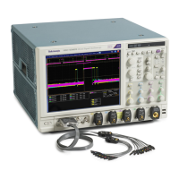
Specifications (MSO70000/C Series, DSA/DPO70000B/C Series, and DPO7000 Series)
Table 1-1: Channel input and vertical s pecifications, all MSO70000/C, DSA/DPO70000B/C, and DPO7000 Series
models (cont.
)
Characteri
stic
Descriptio
n
Step respon
se settling time,
typical,
≥ 4 GHz models
The time by w
hich the step response enters and stays below the indicated % error. Step
transition occurs at the 50% amplitude point of the step leading edge.
DSP off
Instrument
Gain setting (FS) ± Step amplitude Settling
Error
Time
MSO/DSA
/DPO72004C
100 mV
200 mV
500 mV
1V
2V
5V
≤ 100% FS
,
≤50% FS
overdrive
<9%
<5.5%
<2.5%
< 0.15%
150 ps
400 ps
3ns
1ms
MSO/DSA/DPO71604C
100 mV
200 mV
500 mV
1V
2V
5V
≤ 100% FS,
≤ 50% FS
overd
rive
<9%
<5.5%
<2.5%
<0.15%
150 ps
400 ps
3ns
1ms
MSO/DSA/DPO71254C
100 mV
200 mV
500 m
V
1V
2V
5V
≤ 100% FS,
≤ 50%
FS
overdrive
<9%
<5.5
%
<2.5%
< 0.15%
150 ps
400 ps
3ns
1ms
MSO
70804,
DSA/DPO70804B
100 mV
200
mV
500 mV
1V
2V
5V
≤ 10
0% FS,
≤ 50% FS
overdrive
<6%
<3%
<2.5%
<0
.15%
150 ps
600
ps
3ns
1ms
MSO70604,
DSA/DPO70604B
10
0mV
200 mV
500 mV
1V
2V
5V
≤ 100% FS,
≤ 50% FS
ov
erdrive
<6%
<3%
<2
.5%
< 0.15%
20
0ps
800 ps
3ns
1m
s
MSO70404,
D
SA/DPO70404B
100 mV
200 mV
5
00 mV
1V
2V
5V
≤ 100% FS,
≤
50% FS
overdrive
<6%
<
3%
<2.5%
< 0.15%
300 ps
1.2 ns
3
ns
1ms
1–12 MSO70000/C, DSA70000B/C, DPO7000B/C, DPO7000, MSO5000, DPO5000 Series

 Loading...


