Display a wavefo
rm
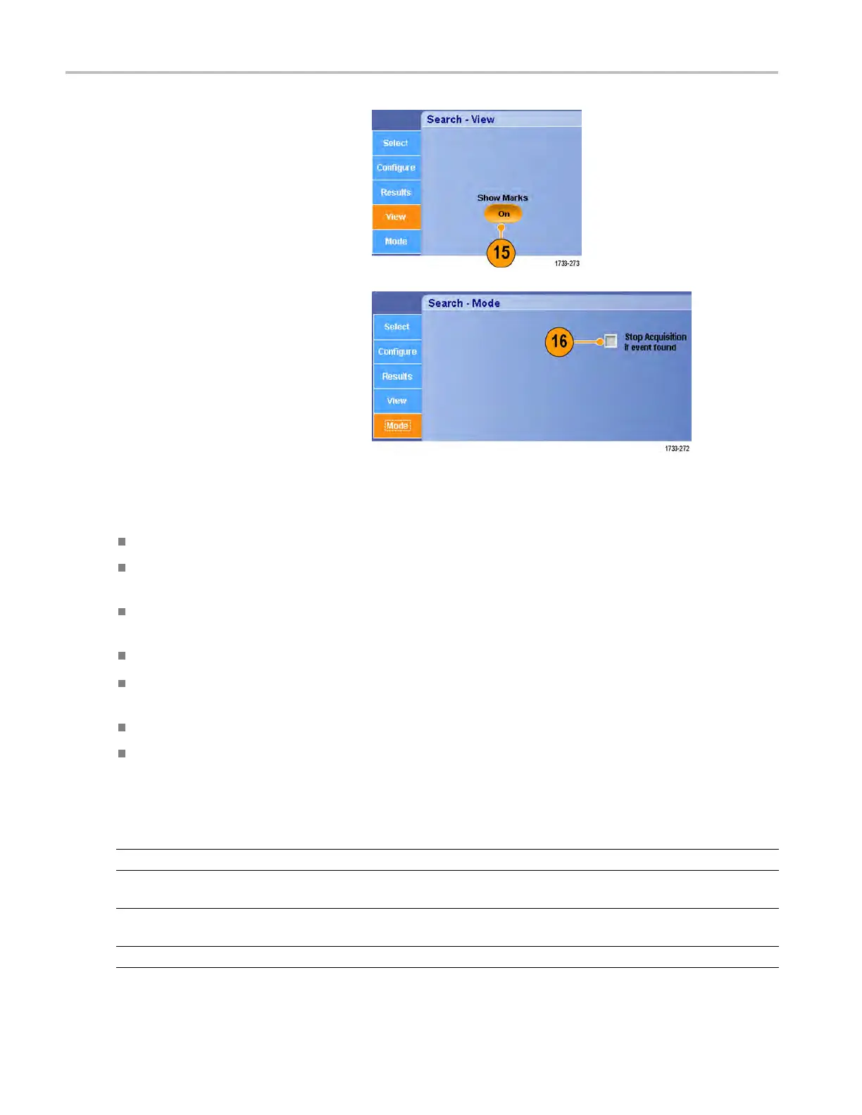
15. To toggle the display of mark triangles on
and off, select the View tab and press
Show Marks.
16. To stop acqu
isitions if a match is found,
select the Mode tab and check Stop
Acquisition if event found.
Quick tips
Search is performed only on acquired data. Set up the instrument to acquire the data y ou are searching for.
Set the sample rate so the search event is discernible. You can search for a glitch that is wider than a couple of
sample
intervals.
You can
copy trigger settings to search for other locations in your acquired waveform that meet the trigger conditions.
You can copy search settings to your trigger.
Edge search marks are created without zoom factors. Other search types create marks with an appropriate zoom factor.
Pressing Bring Zoom to Mark Zoom 2 or Zoom 3 displays the corresponding zoom view with the same zoom parameters
as Zoom 1.
Custom (User) marks are saved with the waveform when the waveform is saved and when the setup is saved.
Automatic search marks are not saved with the waveform when the waveform is saved. However, the search criteria are
save
d in the saved setup, so you can easily recapture the marks by reusing the search function.
Sear
ch includes the following search capabilities:
Search Description
Edge
Searches for edges (rising or falling) with a user-specified threshold level.
Glitch Searches for pulses narrower (or wider) than the specified width, or ignores glitches
narrower (or wider) than the specified width.
Width
Searches for positive or negative pulse widths that are >, <, =, or ≠ a user-specified pulse
width.
Setup & Hold Search for violations of user-specified setup and hold times.
110 MSO/DPO70000DX, MSO/DP O70000C, DPO7000C, and MSO/DPO5000 Series User Manual
 Loading...


