Application exa
mples
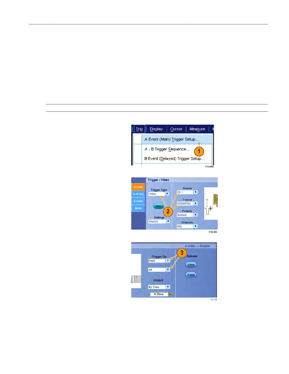
8. Depending on your Trigger On selection,
you m ay need to make additional
selections.
Triggering on a video signal
The instrument supports triggering on NTSC, SECAM, PAL, and high definition signals.
To trigger on the video fields:
NOTE. The video trigger type is available only on DPO7000C, MSO5000, and DPO5000 Series instruments.
1. Select Trig > A Event (Main) Trigger
Setup....
2. Set the A trigger type and source in the
A Event tab.
Select
Format > 525i/NTSC.
3. Select Trigger On > Field.
Select Odd, Even,orAll fields.
MSO/DPO70000DX, MSO/DPO70000C, DP O7000C, and MS O/DPO5000 Series U ser M anual 171
 Loading...


