Acquire the Sign
al
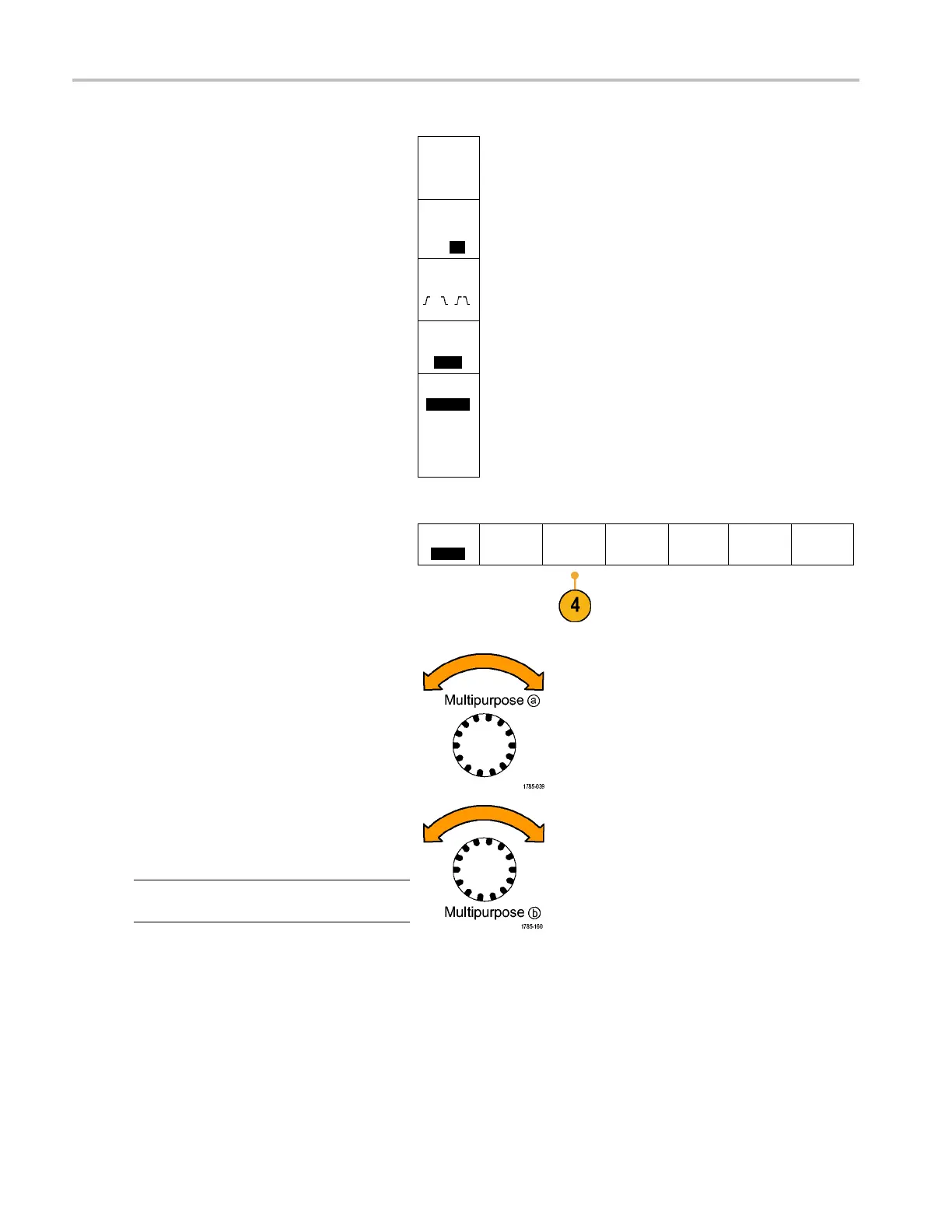
Use the side-bezel buttons to defi ne
parameters for the inputs, such as speci fic
signals to an a
nalog or digital channel.
Define
Inputs
If you select Parallel, push the side-bezel
button to ena
ble or disable Clocked Data.
Clocked
Data
Yes|
No
Push the side
-bezel button to select the
Clock Edge on which to clock data: rising
edge, falling edge, or both edges.
Clock
Edge
Turn multip
urpose knob a to select the
Number of Data Bits in the parallel bus.
Number of
Data Bits
(a) 16
Turn multipurpose knob a to select the
desired bi
ttodefine.
Turn multipurpose knob b to select the
desired analog or digital channel as the
source fo
r the bit.
Define Bits
(a) Bit 15
(b) D15
4. Push Thresholds.
Bus B1
Parallel
Define
Inputs
Thresholds B1 Label
Parallel
Bus
Display
Event
Table
You c an set the threshold for all c hannels in
the parallel or serial bus from a list of preset
values
. The preset values vary, depending
on the bus type.
Alternatively, you can set the threshold to
a speci
fic value for the signals that make
up the parallel or serial bus. To do so,
push the Select side-bezel button and turn
multi
purpose knob a to select a Bit or a
Channel number (Signal name).
Then, turn multipurpose knob b to define the
voltage level above which the oscilloscope
treats the signal as a logic high and below
which as a logic low.
NOTE. Some buses use two thresholds per
channel.
62 MDO4000 Series Oscilloscopes User Manual

 Loading...


