Performance Ve ri fi cation
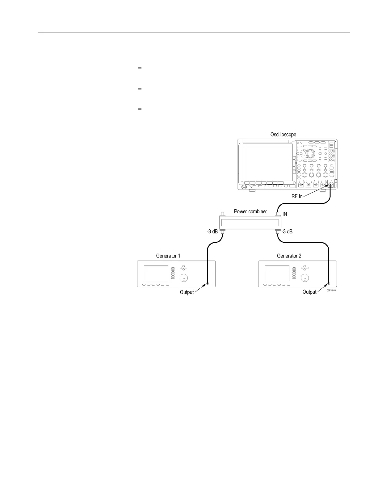
1. Connect the equ
ipment as follows. (See the following figure.)
Connect an SMA cable from the RF input on the oscilloscope to the power
combiner conn
ector labeled “IN.”
Connect an SMA cable from the RF output of a generator to a -3 dB input
on the power
combiner.
Connect an SMA cable from the RF output of the other generator to the
other -3 dB i
nput on the power combiner.
2. Set generator 1 to provide a 2.735 GHz, -5 dBm signal at the RF input of
the oscilloscope.
3. Set generator 2 to provide a 2.755 GHz, -5 dBm signal at the RF input of
the oscilloscope.
4. Initial oscilloscope setup:
a. Push the front-panel Default Setup button.
b. Turn channel 1 off.
c. Push the front-panel RF button to turn on the RF channel and show the
bottom-bezel menu.
d. Turn on the average trace as follows: Push the bottom-bezel Spectrum
Traces button. Push the side-bezel Average button to set the Average
Traces to On. Push the side-bezel Normal button to set Normal to Off.
MDO4000 Series Specifications and Performance Verification 101
 Loading...


