Performance Ve ri fi cation
Check DC Bala n ce
This test check
s the DC balance. You do not need to connect any equipment (other
than a 50Ω terminator) to the oscilloscope to perform this check.
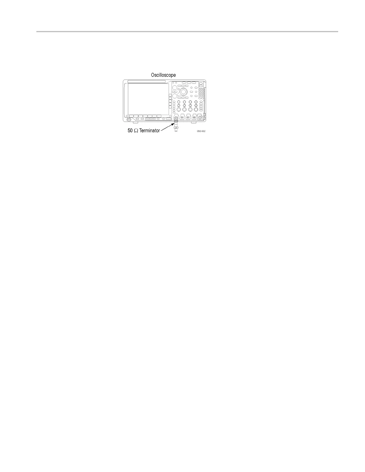
1. Attach a 50 Ω terminator to the oscilloscope channel 1 input.
2. Push the front-panel Default Setup button.
3. Set the input impedance to 50 Ω as follows:
a. Push the channel 1 button.
b. Set the Termination (input impedance) to 50 Ω.
4. Setthebandwidthto20MHz:
a. Push the lower-bezel Bandwidth button.
b. Push the side-bezel button for 20 MHz.
5. Set the Horizontal Scale to 1msper division.
6. Set the Acquisition mode to Average as follows:
a. Push the front-panel Acquire button.
b. Push the Average side bezel button.
c. Make sure that the number of averages is 16.
7. Set the trigger source to AC line as follows:
a. Push the Trigger Menu front-panel button.
b. Select the AC Line trigger source.
8. Set the Vertical Scale to 1mVper d ivision.
9. Select the m ean measurement (if not already selected) as follows:
a. Push the front-panel Wave Inspector Measure button.
b. Push the Add Measurement lower b ezel button.
c. Select the Mean measurement.
d. Push the OK Add Measurement side-bezel button.
e. View the Mean measurement value in the display.
MDO4000 Series Specifications and Performance Verification 65