Performance Verification
Check Delta Time
Measurement Accuracy
This test check
s the Delta-time measurement accuracy (DTA) for a given
instrument setting and input signal.
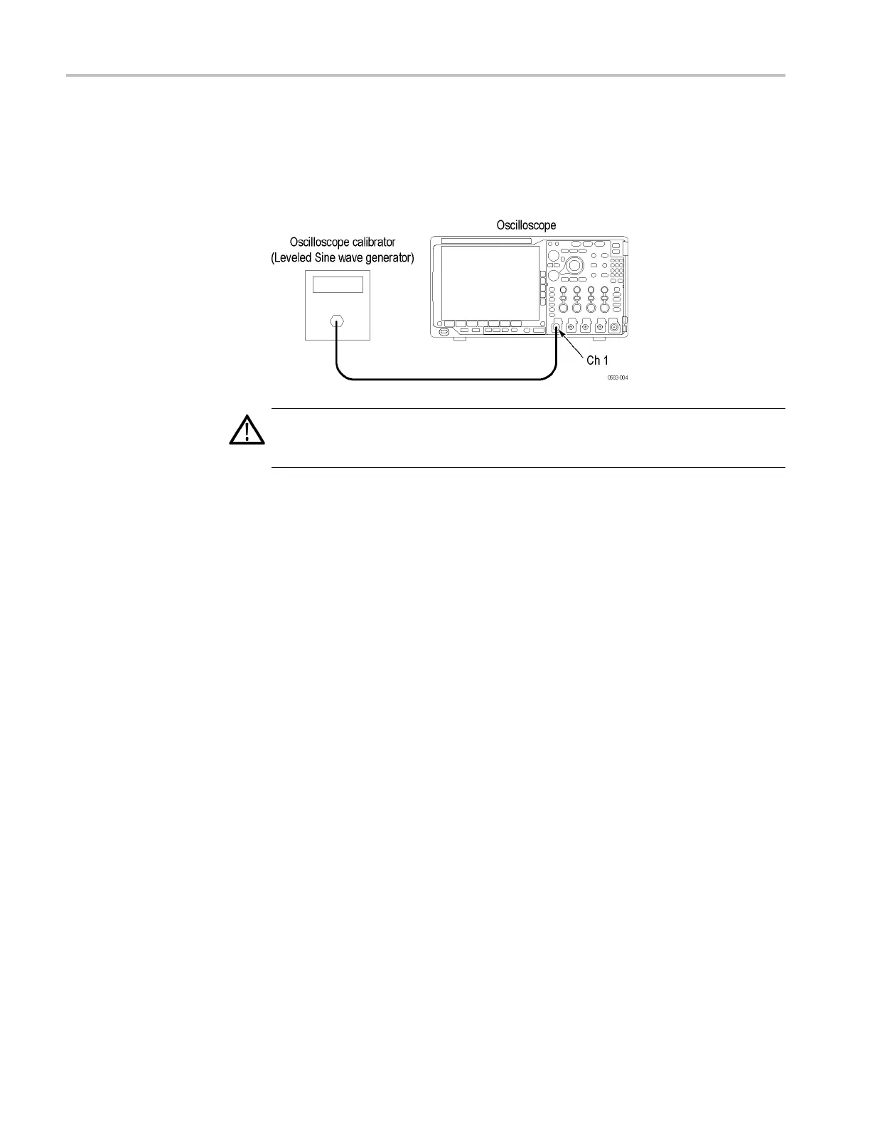
Connect a 50 Ω c
oaxial cable from the signal source to the oscilloscope channel 1,
as shown in the following illustration.
WARNING.
The generator is capable of providing dangerous voltages. Be sure to
set the generator to off or 0 volts before connecting, disconnecting, and/or moving
the test hookup during the performance of this procedure.
2. Push the oscilloscope front-panel Default Setup button.
3. Select
50 Ω impedance a s follows:
a. Set the sine wave generator output impedance to 50 Ω.
b. Push the channel 1 button to display the channel 1 m enu.
c. Set the Termination (input impedance) to 50 Ω.
4. Set the trigger sour ce to channel 1 as follows:
a. Push the Trigger Menu button.
b. Pus
htheSource lower-bezel button (if not already selec ted).
c. Select channel 1 (if not already selected).
5. Set the Mean & St Dev Samples to 100 as follows:
a. Push the Wave Inspector Measure button.
b. Push the bottom-bezel Add Measurement button.
c. Select the Burst Width measurement.
d. Push the side-bezel OK Add Measurement button.
e. Push the bottom-bezel More button to select Statistics.
f. Set the Mean & Std Dev Samples to 100, as shown in the side menu.
80 MDO4000 Series Specifications and Performance Verification