Input signal requirements
Keep the input signals within allowed limits to ensure the most accurate measurements and prevent damage to the analog and
digital probes or instrument.
Make sure that input signals are within the following requirements.
Input Description
Analog input channels, 1 M Ω setting, maximum input voltage
at BNC
300 V
RMS
Measurement Category II
Analog input channels, 50 Ω setting, maximum input voltage at
BNC
5 V
RMS
Digital input channels, maximum input voltage range at digital
inputs
Observe probe ratings
TLP058; ±42 V
P
Ref In maximum input voltage at BNC (rear panel) 7 V
PP
AUX trigger input ±5 V
RMS
Installing the instrument in a rack
Use these instructions to install the MSO58LP into a standard 19" equipment rack.
The MSO58LP comes equipped with the rack bracket hardware installed on the chassis. You will need to install the rear rack
brackets in the rack. The instrument ships with a bag of assorted bolts and washers for installing the instrument in the most
common rack types.
To use an MSO58LP on a bench, purchase and install the MSO58LP Benchtop Conversion kit (Tektronix part number 020-3180-
xx). The kit includes chassis feet and a handle, and lets you stack instruments on a bench.
Follow these steps to install the instrument in a rack:
WARNING. To prevent injury, two people are required to install the instrument.
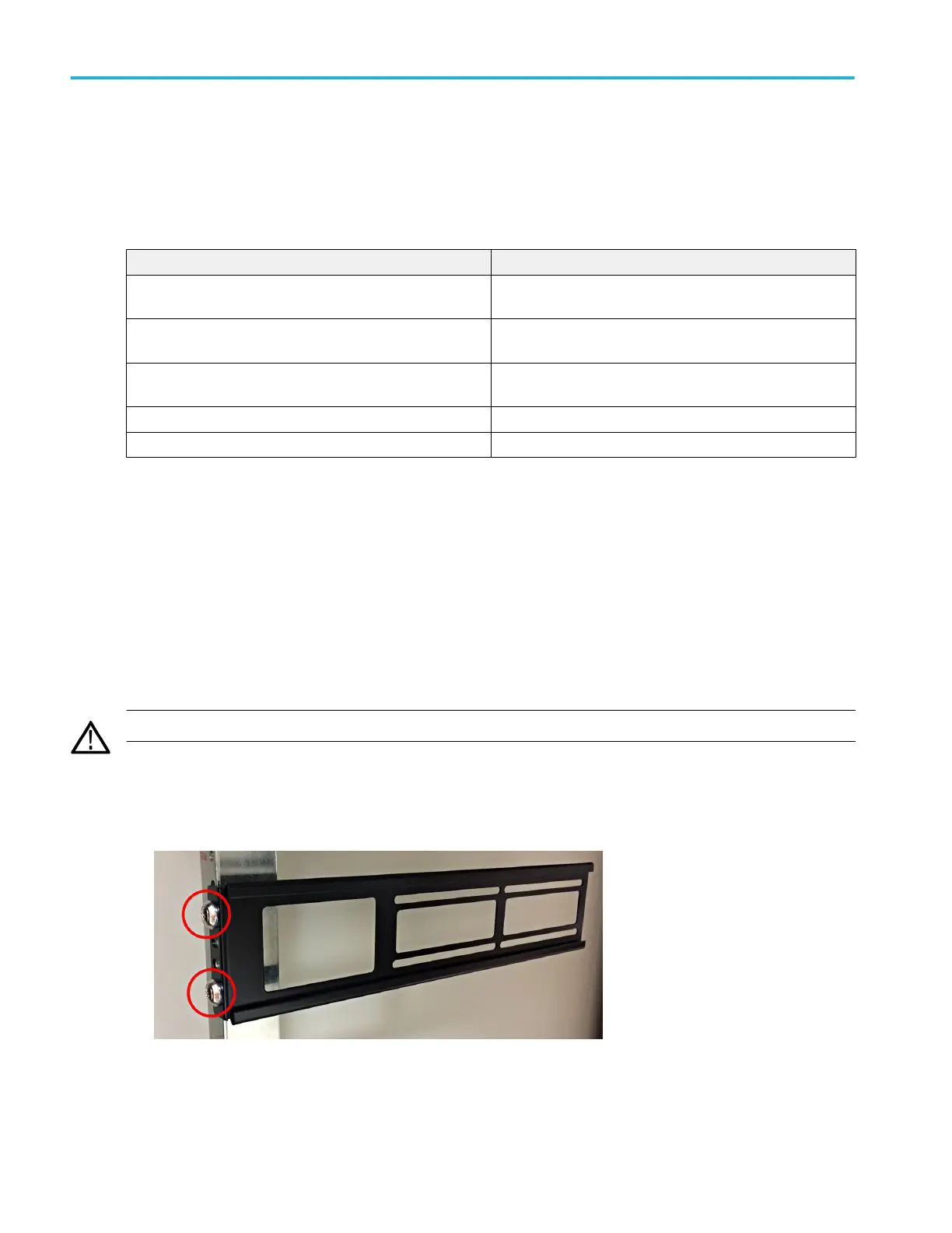
1. Use two bolts and washers from the supplied hardware to attach one of the rear rack brackets to the rear of the rack.
Tighten by hand.
2. Using two people to support the instrument, insert the instrument from the front of the rack so that the chassis rack bracket
inserts into the rear rack bracket.
3. Continue pushing from the front until the instrument is flush with the front of the rack.
Installing your instrument
2 MSO58LP Installation and Safety Manual

 Loading...


