Quickly display a waveform (Autoset)
The Autoset function analyzes the signal characteristics and changes the instrument Horizontal, Vertical, and Trigger settings to
automatically display a triggered waveform. You can then make further changes to trigger and horizontal settings to view the
waveform point of interest.
1. Connect the probe with the signal of interest to the lowest-numbered channel. The signal can be analog or digital.
2. Connect any other associated signal(s) to available channel input(s).
3. Add the channel waveforms to the Waveform view. Add a channel waveform to the display on page 33
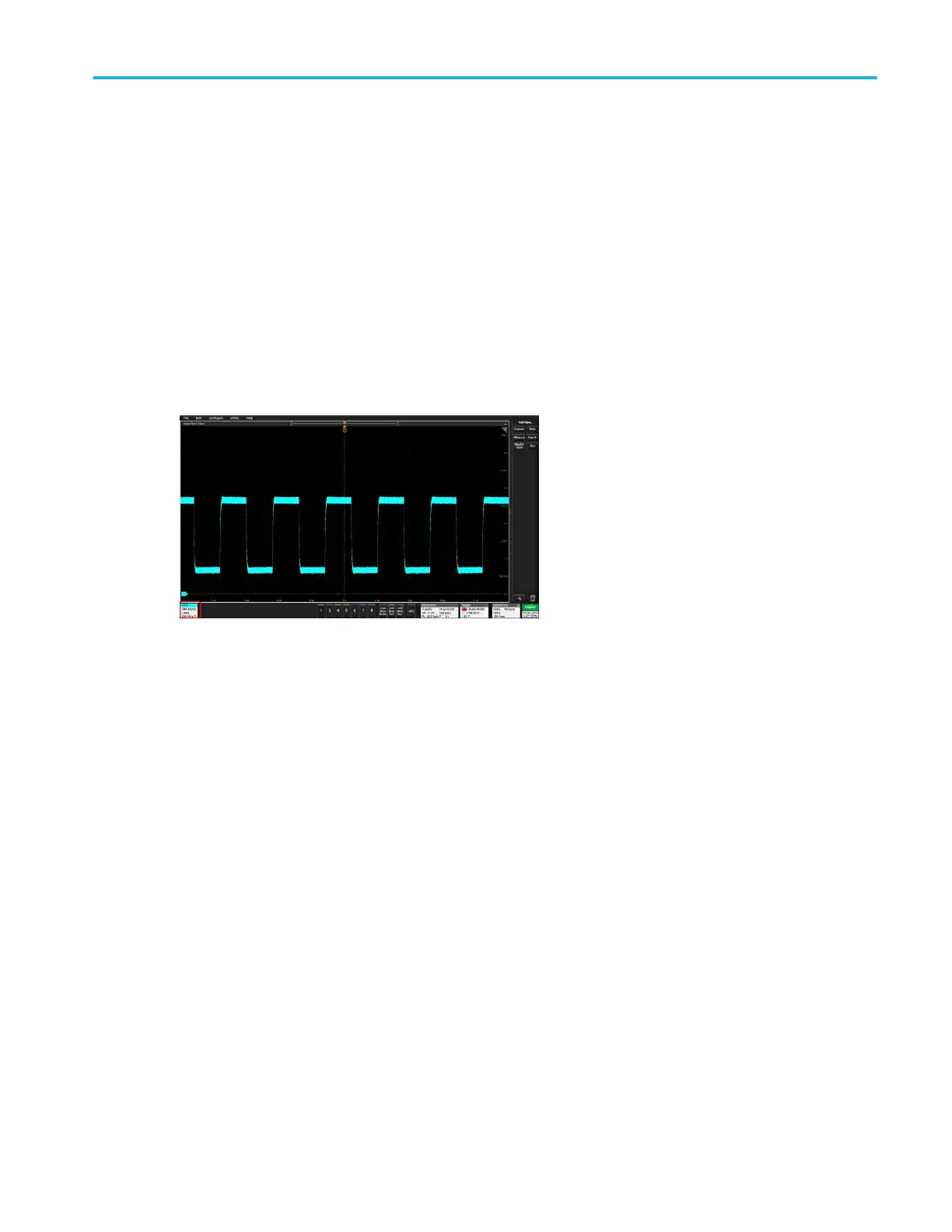
4. Push the front-panel Autoset button. When using the Stacked Display mode, the instrument analyzes the signal
characteristics of the lowest-numbered displayed channel (analog or digital) and adjusts the horizontal, vertical, and trigger
settings accordingly to display a triggered waveform for that channel. Vertical scale is adjusted for all other active
waveforms to maximize ADC utilization.
When using the Overlay Display mode, the instrument adjusts the horizontal and trigger settings of the lowest-numbered
displayed channel to display a triggered waveform for that channel, and adjusts the vertical settings and position of all active
waveforms such that they are uniformly spaced on screen.
Autoset guidelines:
■
Autoset displays two or three cycles (depending on the detected signal) with the trigger level near the midlevel of the signal.
■
The trigger is set to type Edge, rising slope, DC coupling.
■
If no channels are displayed before pushing Autoset, the oscilloscope adds Ch 1 to the view whether it has a signal or not.
■
For digital signals, the oscilloscope analyzes and triggers on the lowest (LSB) digital channel with an active signal.
■
Autoset ignores math, reference, and bus waveforms.
■
A channel or waveform with a frequency less than 40 Hz is classified as no signal.
Operating basics
MSO54, MSO56, MSO58 Installation and Safety Manual 35
 Loading...


