Maintenance
AC Power Supply
module
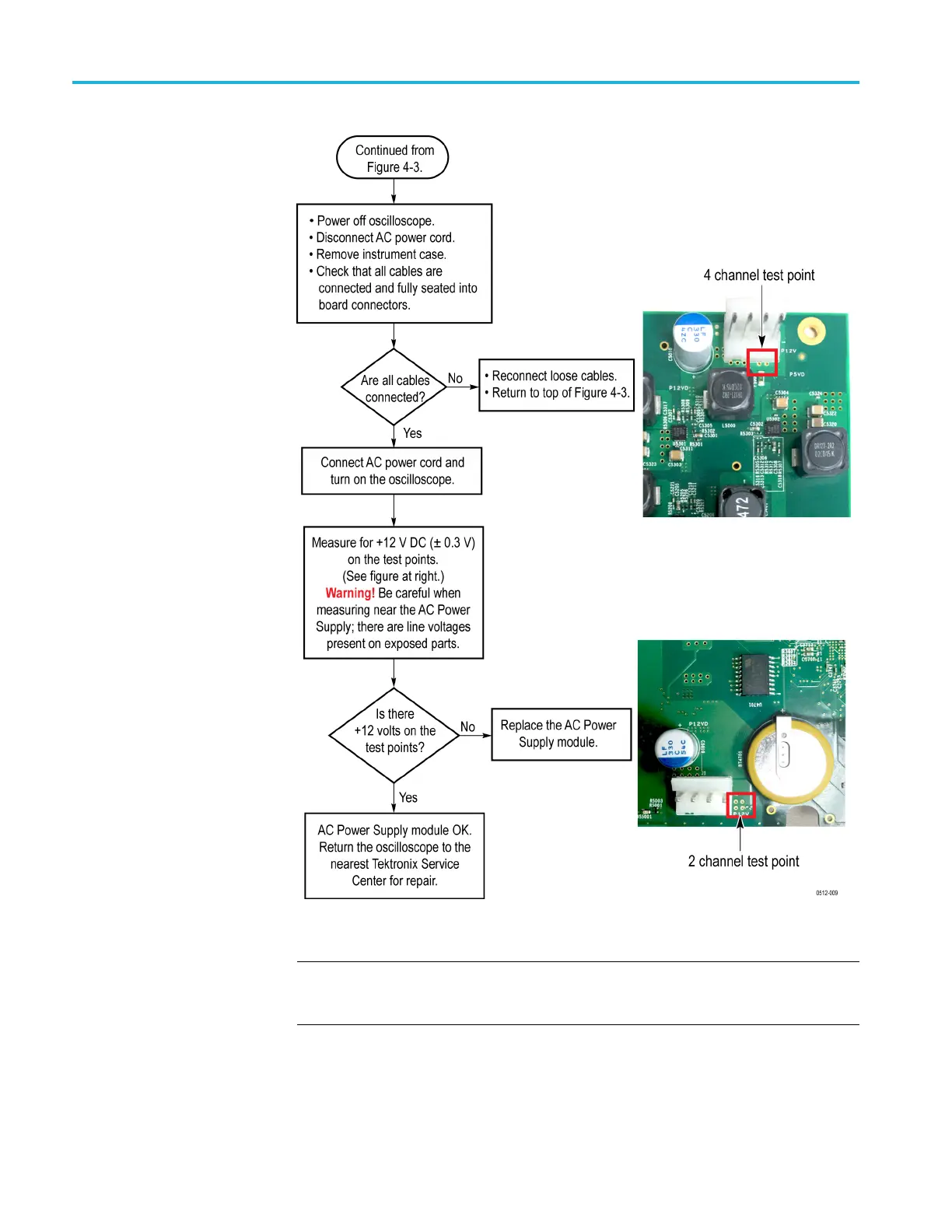
troubleshooting flowchart
Figure 4-2: AC Power Supply module troubleshooting
NOTE. Images show the power supply cable disconnected from the main board, to
better show the test point locations. The power cable from the Power Supply must
be connected to the Main board to test the +12 VDC value.
4–8 TBS2000 Series Service Manual

 Loading...


