TCPA300 and TCPA400 Performance Verification
Bandwidth
This procedure tests the bandwidth of the TCPA300 and TCPA400 amplifiers. In
this test you measure a signal at a relatively low frequency and again at the upper
test frequency. The two measurements are compared to verify that the signal
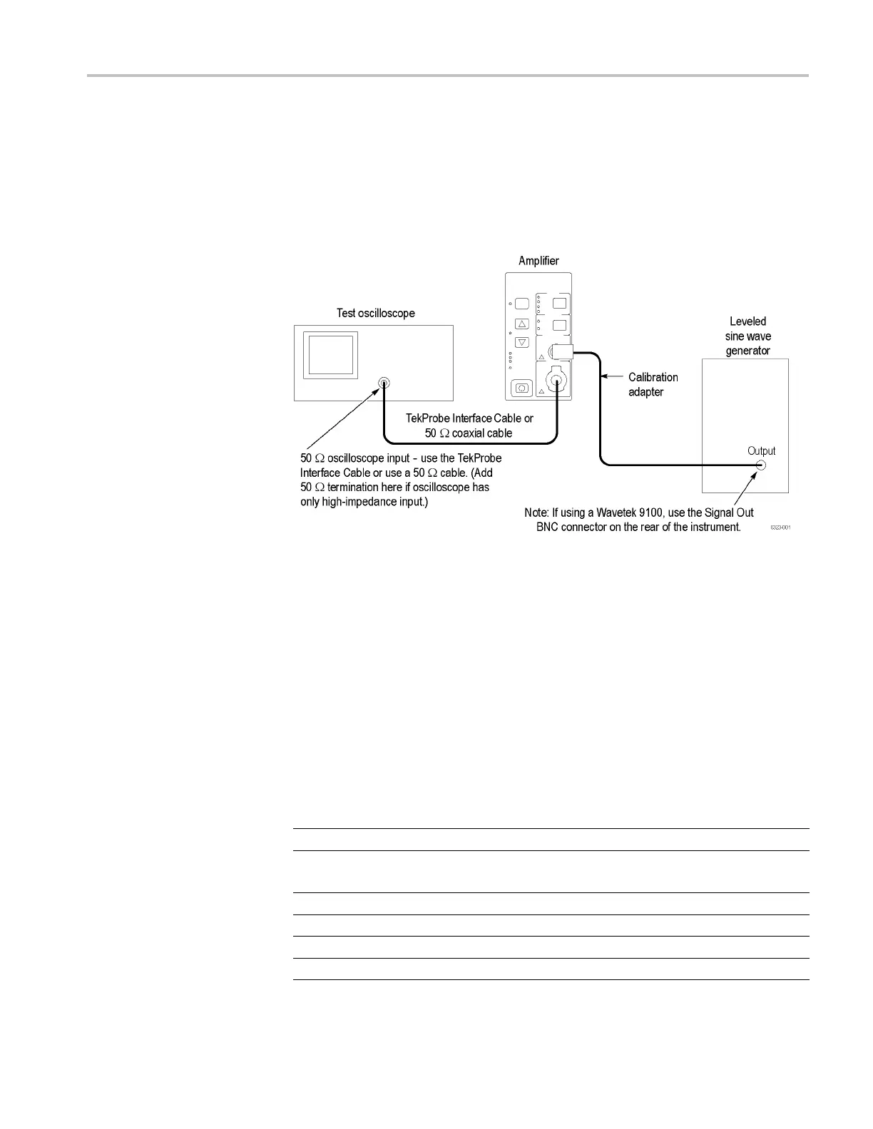
amplitude does not fall below a certain limit. Use the equipment connections
shown.
Figure 3: B andwidth test setup
1. If you are using a Tektronix oscilloscope that supports the TekProbe Level 2
Interface, use the TekProbe Interface Cable to connect the amplifier OUTPUT
to the oscilloscope input. If you are not using a Tektronix oscilloscope that
supports the TekProbe Level 2 Interface, use a 50 Ω BNC cable. If the
input impedance of your oscilloscope is 1 M Ω, connect a 50 Ω feedthrough
termination at the oscilloscope i nput. Do not connect the termination at the
amplifier output.
2. Connect the Calibration Adapter to the amplifier PROBE INPUT.
3. Make or verify the equipment settings: (See Table 6.)
Table 6: Equipment settings for bandwidth check
Oscilloscope
Vertical input impedance
50 Ω
Time base
TCPA300
TCPA400
40 ns/division
80 ns/division
Record length 500
Coupling DC
Offset 0 V (mid-sca le)
Trigger type Edge
TCPA300/400 Amplifiers and TCP300/400 Series Current Probes Service Manual 9
 Loading...


