TCP305 and TCP312 Performance Verification
The measured ri
se time (t
r
measured) is the value calculated in step 5.
The system rise time (t
r
system) is the rise time of the displayed signal when
output of the p
ulse generator is connected directly to the oscilloscope input. (The
current probe and amplifier are excluded.)
7. Verify that
the p robe rise time is less than the warranted specification listed
in the test record.
8. Record the r
esults on the test record.
9. Disconnect the probe from the pulse generator.
Bandwidth
This procedure tests the bandwidth of the TCP305 and TCP312 Current Probes.
In this t
est you measure a signal at a relatively low frequency and again at the
rated bandwidth of the probe. The two measurements are compared to verify
that the signal amplitude does not fall below -3 dB at the probe bandwidth. The
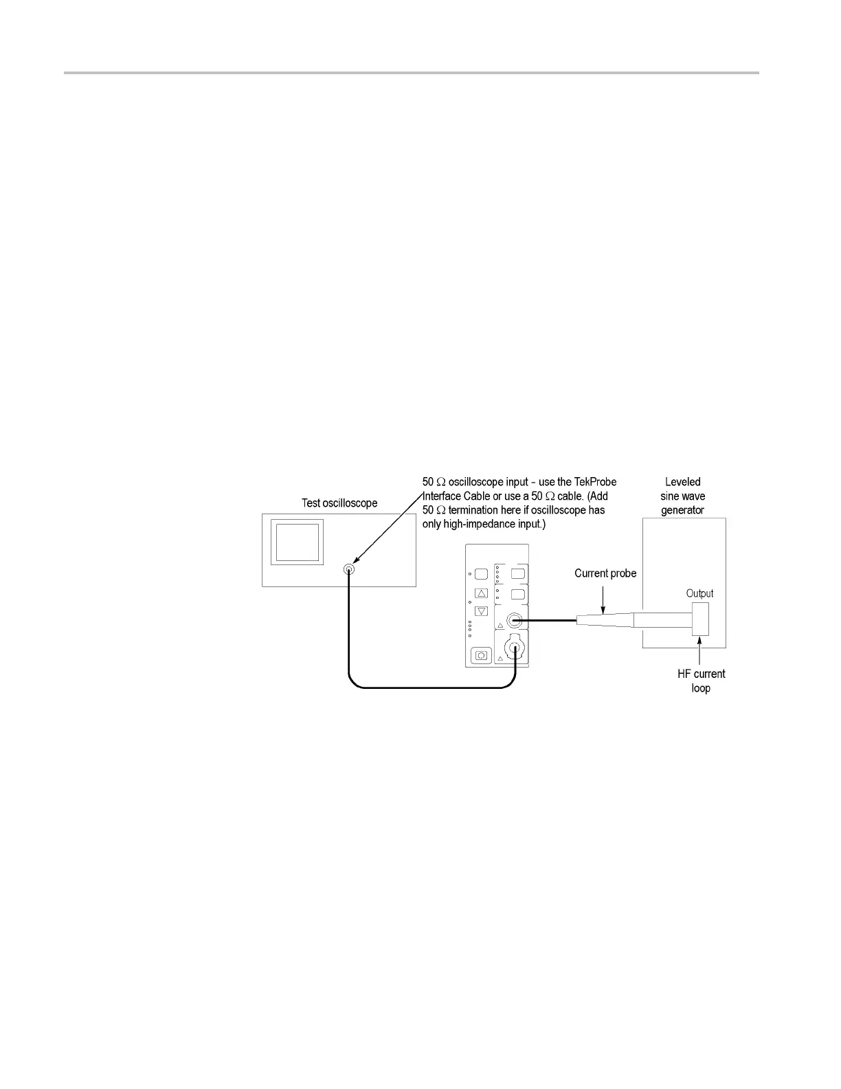
equipment connections are shown below. (See Figure 9.)
Fig
ure 9: Bandwidth test setup for TCP305 and TCP312
Equipment Connections
1. If you are using a Tektronix oscilloscope that supports the TekProbe Level 2
In
terface, use the TekProbe Interface Cable to connect the amplifier OUTPUT
to the oscilloscope input. If you are not using a Tektronix oscilloscope that
supports the TekProbe Level 2 Interface, use a 50 Ω BNC cable. If the
input impedance of your oscilloscope is 1 MΩ, connect a 50 Ω feedthrough
termination at the oscilloscope input. Do not connect the termination at the
2. Connect the current probe to the amplifier PROBE INPUT.
3. Connect the HF current loop to the output of the leveled sine wave generator.
26 TCPA300/400 Amplifiers and TCP300/400 Series Current Probes Service Manual
 Loading...


