TCPA300 and TCPA400 Performance Verification
Current Overl
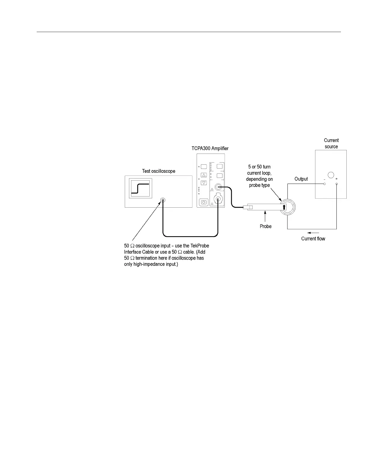
oad Test (TCPA300 Only)
This test checks the functionality of the TCPA300 current overload detection
circuit using the setup shown. You set the current source to output the maximum
rated curren
t for the probe/amplifier you are testing, and then increase the current
source to a level that engages the overload circuit (the OVERLOAD LED is on).
Then, you repeat the test at the opposite polarity.
This test uses current loops that you make using wire and 3-inch forms.
Instructions on making current loops are available. (See page 4, Making DC
Current Loops.)
Figure 6: Overload test setup
1. Connect the circuit as shown. (See Figure 6.) The correct current loop to use
for the probe you are testing is available. (See Table 10 on page 16.)
2. Set the RANGE on the amplifier to the highest setting for the probe that is
connectedtotheamplifier.
3. Adjust the current source output to the value for the probe you are testing.
(See Table 10 on page 16.) For example, if you are testing a TCP305, adjust
the output to 10 A.
4. Check that the OVERLOAD LED is off.
TCPA300/400 Amplifiers and TCP300/400 Series Current Probes Service Manual 15
 Loading...


