Appendix A: Specifications
TDS 200-Series Digital Oscilloscope User Manual
93
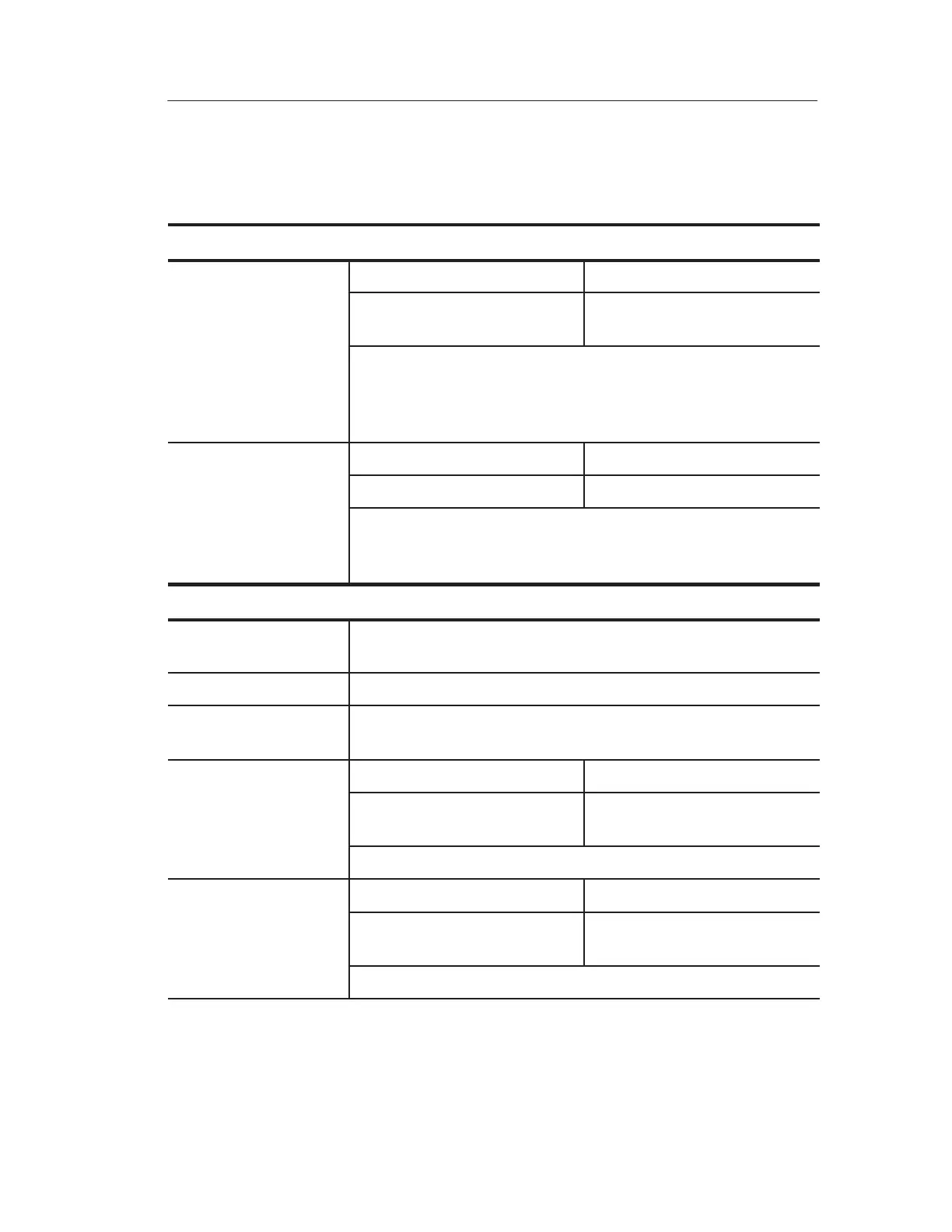
Specifications (Cont.)
Inputs
Channel-to-Channel TDS 210 TDS 220 and TDS 224
Common Mode
Rejection, typical
100:1 at 60 Hz
20:1 at 30 MHz*
100:1 at 60 Hz
20:1 at 50 MHz*
Measured on MATH Ch1 – Ch2 waveform, with test signal
applied between signal and common of both channels, and with
the same VOLTS/DIV and coupling settings on each channel.
Also measured on MATH Ch3 – Ch4 waveform for the TDS 224.
Channel-to-Channel TDS 210 TDS 220 and TDS 224
Crosstalk
≥ 100:1 at 30 MHz*
≥ 100:1 at 50 MHz*
Measured on one channel, with test signal applied between
signal and common of the other channel, and with the same
VOLTS/DIV and coupling settings on each channel.
Vertical
Digitizers 8-bit resolution (except when set to 2 mV/div), each channel
sampled simultaneously
VOLTS/DIV Range 2 mV/div to 5 V/div at input BNC
Position Range 2 mV/div to 200 mV/div, ±2 V
> 200 mV/div to 5 V/div, ±50 V
Analog Bandwidth in TDS 210 TDS 220 and TDS 224
Sample and Average
modes at BNC or with
60 MHz* (when vertical scale
set to > 5 mV/div)
100 MHz* (when vertical scale
set to > 5 mV/div)
P2100 probe, DC
Coupled
20 MHz* (when vertical scale set to ≤ 5 mV/div)
Analog Bandwidth in TDS 210 TDS 220 and TDS 224
Peak Detect mode
(5 s/div to 5 ms/div**),
50 MHz* (when vertical scale
set to > 10 mV/div)
75 MHz* (when vertical scale
set to > 10 mV/div)
typical
20 MHz* (when vertical scale set to ≤ 10 mV/div)
* Bandwidth is not valid for the P2100 probe when the switch is set to 1X.
** The oscilloscope reverts to Sample mode when the sec/div (horizontal scale) is
set from 2.5 ms/div to 5 ns/div. The Sample mode can still capture 10 ns glitches.

 Loading...


