Theory of operation
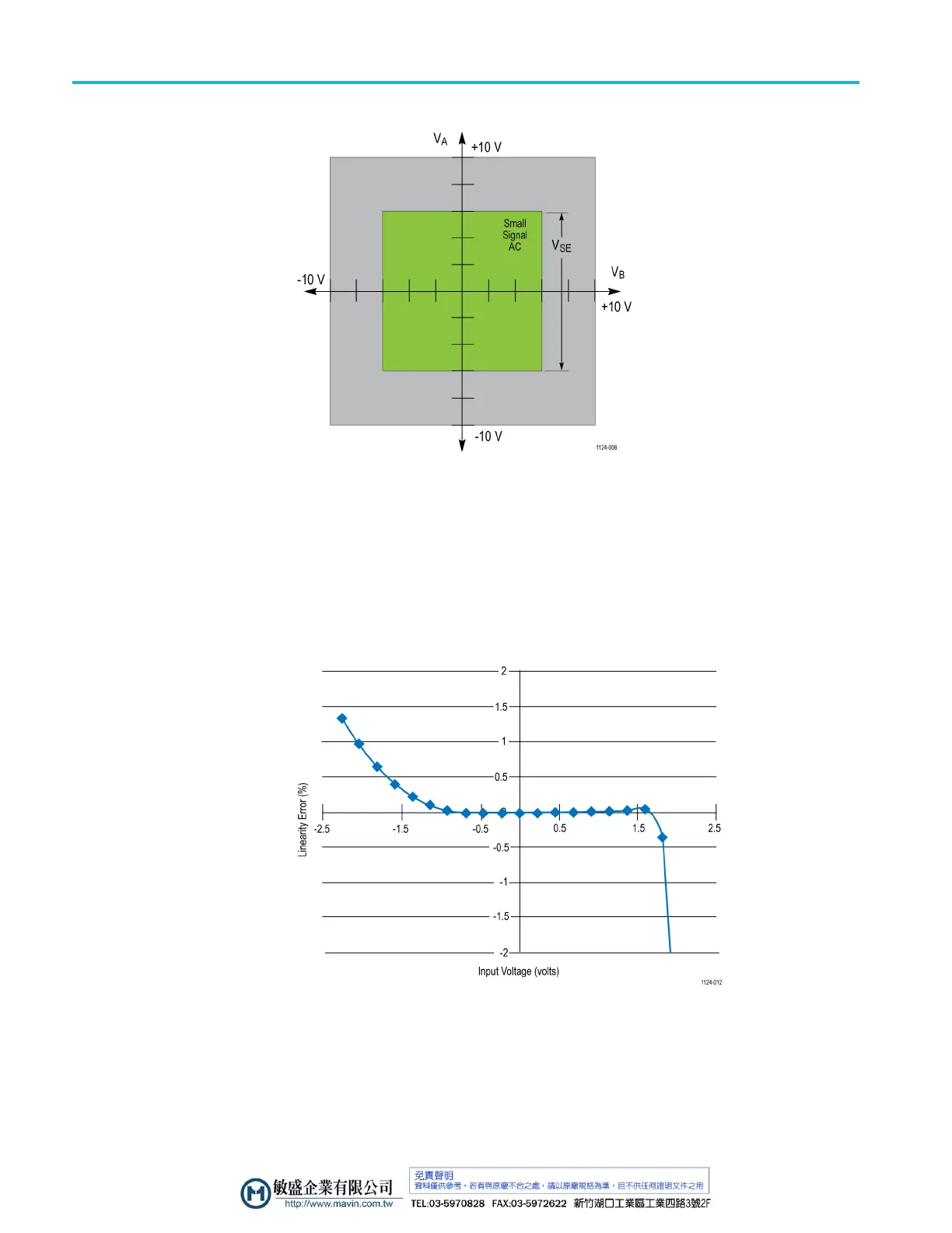
Figure 8: Operating voltage window (P77BRWSR)
Input si
gnal dynamic range
The input signal dynamic range is the maximum voltage difference between the A
and B inputs of the probe tip and the probe tip ground reference that the probe can
accept without distorting the signal. The distortion from a voltage that exceeds
this ma
ximum can result in a clipped or otherwise inaccurate measurement. The
following figure shows the typical linearity error over the dynamic voltage range
of a probe solder tip for the A and B tip inputs.
Figure 9: Dynamic range linearity error plot
16 P7700 Series TriMode Probes Technical Reference

 Loading...


