Theory of operation
There are four m
anual offset voltage value entry fields which also display the
current offset voltage settings. Although all four offset voltage value entry fields
are a ctive, only two of the control pairs are independent.
The manual controls interact with each other as follows:
Adjusting t
he A or B settings affects the Differential and Common settings:
Differential = (A – B)
Common = (A + B)/2
Adjusting the Differential or Common settings affects the A and B settings:
A = Common + (Differential/2)
B = Common – (Differential/2)
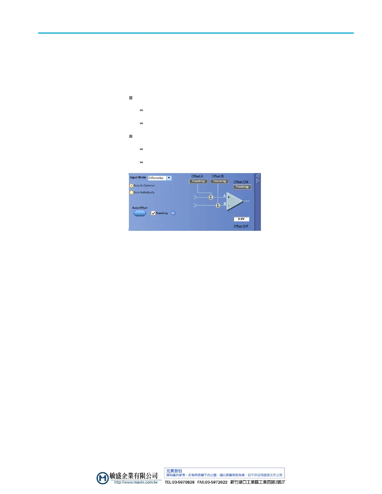
Figure 11: Probe setup screen
There are two Auto Offset modes that can be selected with a radio button
selection: Auto in Common or Auto Individually. Both modes operate by sensing
the average value of the common-mode voltage on the A and B input signals.
Whe
n the Auto in common mode is selected and the Auto Offset button is pushed,
the A and B offset values are both set to the mean value between the sensed A
and B input signal levels. When the Auto Individually mode is selected and the
Auto Offset button is pushed, the A offset value is set to the average value of the
sensed A input signal level and the B offset value is set to the average value of
the sensed B input signal level.
The p robe A and B signal inputs are sensed, monitored, and averaged by probe
internal circuitry and the sensed values are used to automatically set the Offset
V
oltage. The Auto Offset circuitry is shown in simplified form in the figure below.
P7700 Series TriMode Probes Technical Reference 19

 Loading...


