Reference
Common-m ode rejection
ratio
Differential a
mplifiers cannot reject all of the common-mode signal. The ability
of a differential amplifier to reject the common-mode signal is expressed as the
common-mode rejection ratio (CMRR).
The DC CMRR is the differential-mode gain (A
DM
) divided by the common-mode
gain (A
CM
). It is expressed either as a ratio or in dB:
AC CMRR for the probe is determined using 3-port, mixed-mode S-parameters
for the measured differential mode response, where A input = S1, B input = S2
andOutput=S3isdefined as:
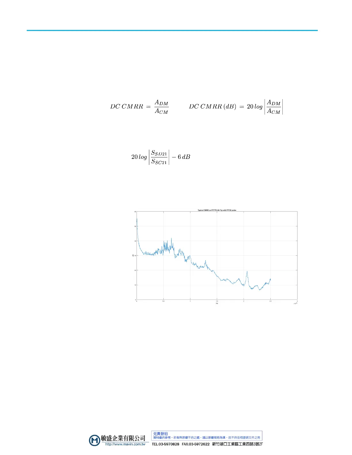
The 6 dB term in the AC CMRR equation gives the voltage-referenced response.
CMRR genera lly is highest (best) at DC and degrades with increasing freque nc y.
A typical CMRR plot for a P7700 Series probe and a flex circuit-based solder
tip is shown.
Figure 2 3: Typical CMRR
Assessing CMRR error
The CMRR of the P7700 Series probes is shown in graphs assuming a sinusoidal
common-mode signal. A quick way to assess the magnitude of CMRR error
when the common-mode signal is not sinusoidal is to connect both leads to the
same point in the circuit. The o scilloscope displays only the common-mode
component that is not fully rejected by the probe. While this technique might not
yield accurate measurements, it allows you to determine if the magnitude of the
common-mode error signal is significant. When using the solder-in tips, keep the
tip leads the same length to maximize the probe CMRR.
34 P7700 Series TriMode Probes Technical Reference

 Loading...


