Reference
Input impedance effec ts on
CMRR
Thelowerthein
put impedance of the probe relative to the source impedance,
thelowertheCMRRforagivensourceimpedance imbalance. Differences
in the source impedance driving the two inputs lowers the CMRR. Note that
single-ended measurements generally result in asymmetric source impedances
which tend to reduce the differential mode CMRR.
Differential-mode rejection
When making common-mode signal measurements ((A+B)/2 – GND) with the
TriMode probe, it is desirable to reject the differential-mode signal present
between the two inputs. This rejection is expressed as the Differential-Mode
Rejection Ratio (DMRR).
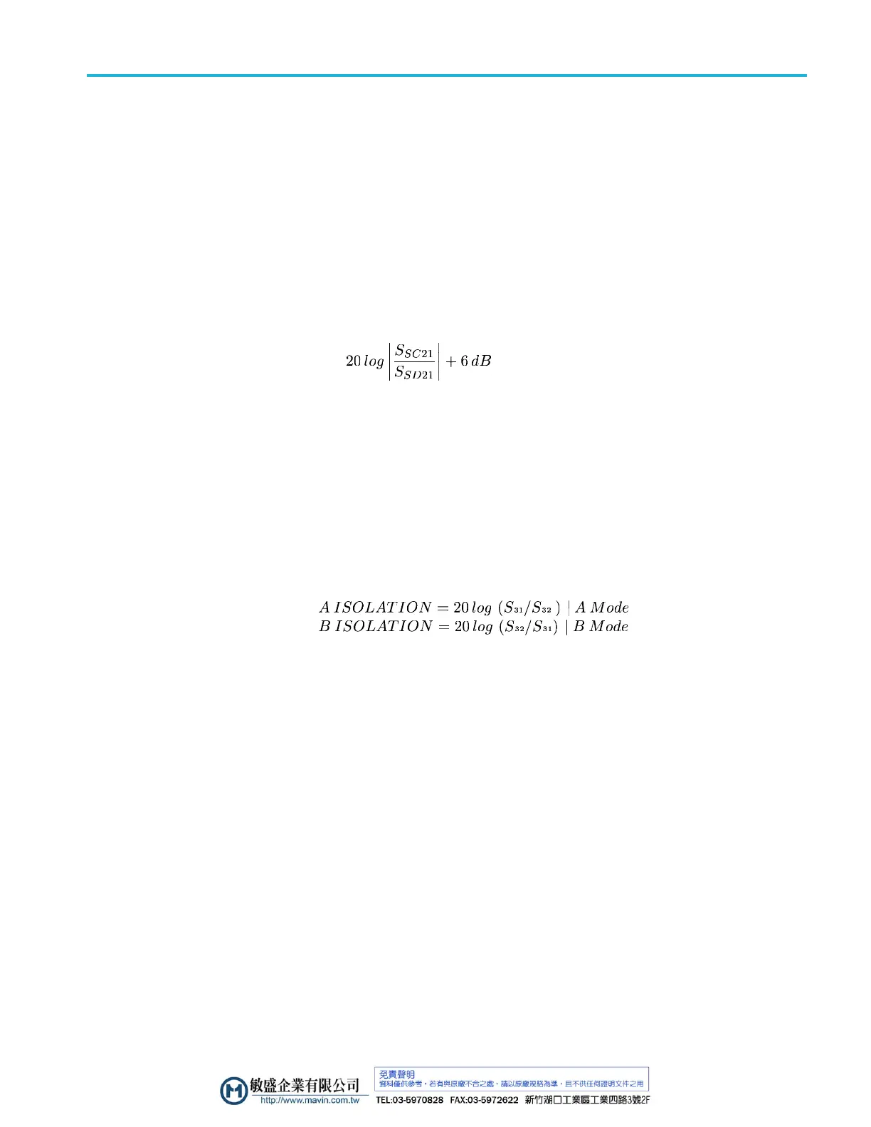
AC DMRR for the probe is defined using 3-port, mixed-mode S-parameters as:
for the measured
common mode response. The 6 dB term in the AC DMRR
equation gives the voltage-referenced response.
Channel isolation
Under ideal conditions when taking single-ended measurements with a differential
probe, no part
of a signal a pplied to one input of the probe would appear on the
other input. In reality some portion of the signal on one input does “bleed” over to
the other input, and this effect increases with frequency. Channel isolation is a
measure of how much crosstalk occurs between the two probe inputs. The channel
isolation is defined with S-parameter measurements below, where:
A input = S1, B input = S2, O utput = S3
P7700 Series TriMode Probes Technical Reference 35

 Loading...


