AFA4000/E VAV Airflow Controller / p.115
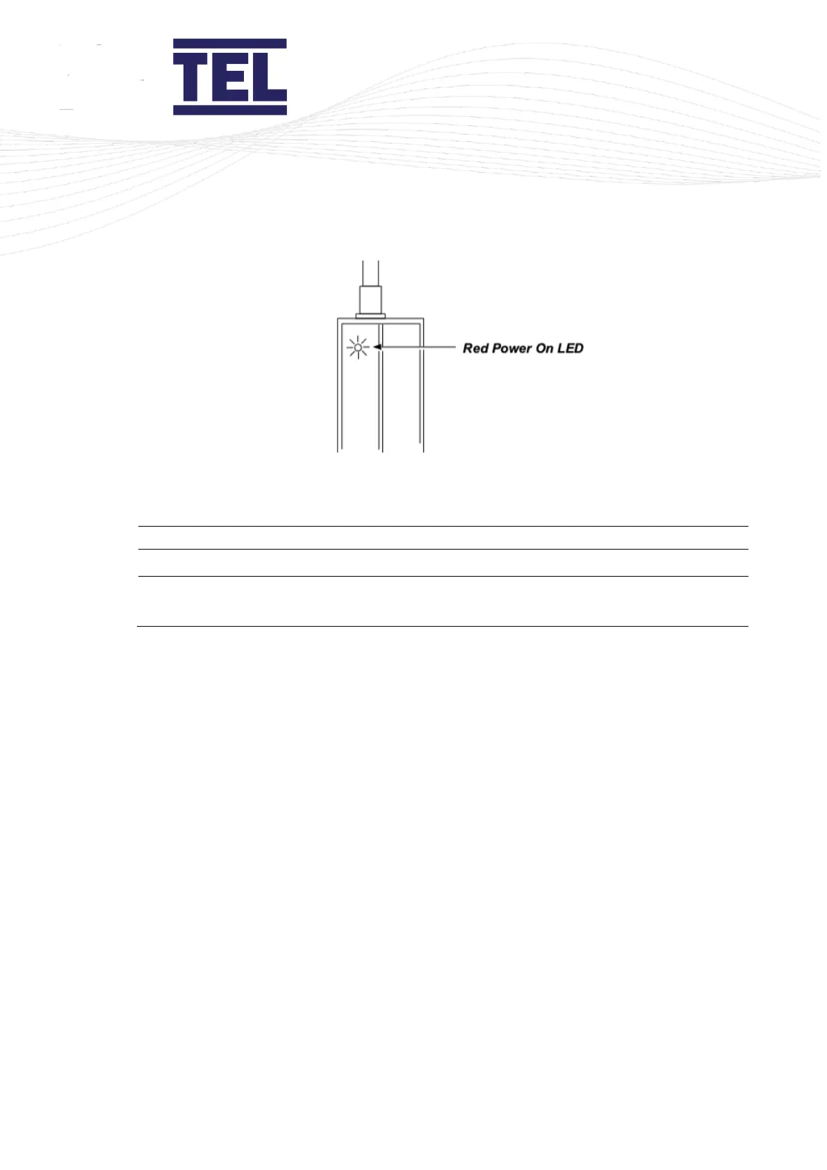
Figure 64: Red Power On LED
6. Ensure that Switch 1 (sw1), see Figure 54, is set to the correct range:
7. Ensure that Switch 2 (sw2) (Figure 63) is set to Off (Operation Mode).
8. Ensure that Switch 3 (sw3) is set to On (Normal Operation).
9. Set Switch 4 (sw4) to On. A buzzer will then sound when the beam is broken, this aids the
setting up of the beam.
The signal LED indicates beam status:
• Green if the detection area is clear.
• Red if the area is not clear.
10. Turn the gain potentiometer anti-clockwise, to the minimum. The transmitter and receiver
can no longer sense each other.
11. Slowly adjust the gain potentiometer (Figure 63) clockwise (to maximum) until the
transmitter and receiver can sense each other, for example, the receiver can detect the
beam sent from the transmitter.
12. Set sw3 to Off to store the settings.
13. Turn the gain potentiometer approximately 5 degrees clockwise to ensure sufficient gain.
14. Use a glass object to test whether it breaks the beam. Do this across the entire open face of
the fume hood.
If the glass object does not break the beam, adjust the gain potentiometer counter-clockwise
until inserting the glass object breaks the beam.
15. If required, set sw4 to Off to disable the buzzer.