AFA4000/E VAV Airflow Controller / p.84
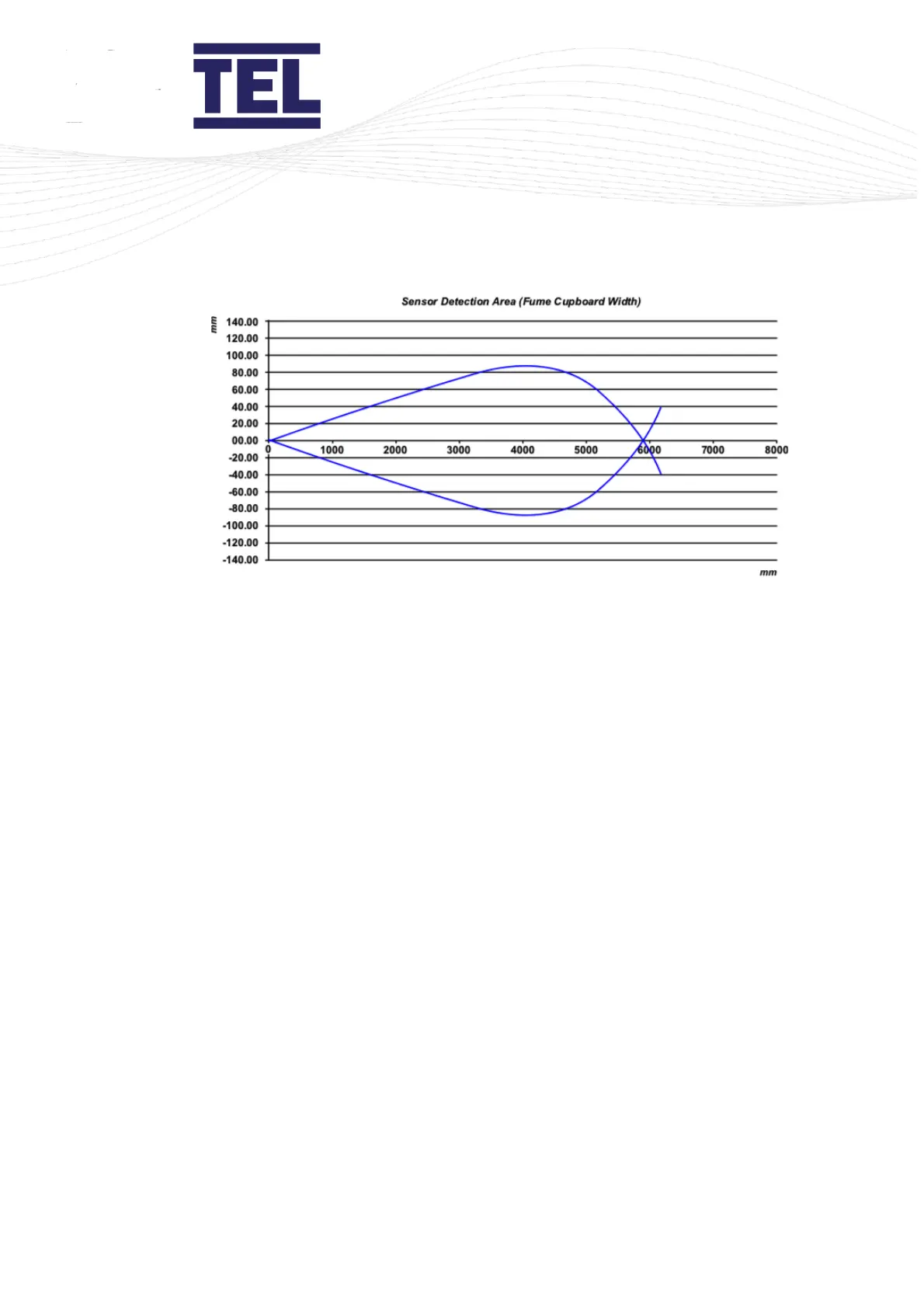
Figure 49: Maximum under sash sensor offset
For example, on a 1000 mm wide Fume Hood the sensor can detect the retro-reflective strip
up to ± 20 mm either side of the Under Sash Sensor's centreline.
4. Connect to the Auto Sash Control Unit. See the wiring schematic in section 6.9.
6.5 Tilt switch
Tilt Switches are provided in a variety of forms, the installation instructions that follow are
therefore general.
• Ensure that the Tilt Switch is installed in the correct orientation – ‘open’ when the front
panel is closed and ‘closed’ when the front panel is open.
• Connect the Tilt Switch to the Auto Sash Control Unit. See the wiring schematic in section
6.9 and Figure 50.
• Link out / connect the relevant terminals on the Auto Sash Control Unit when not using a
Tilt Switch. See the wiring schematic in section 6.9 and Figure 50.